Production Testing
Overview
The purpose of the test procedure is to identify connectivity issues, poor soldering, and potential manufacturing defects. Some of the issues are directly identified by explicit part-targeted tests, others are implicit, by running adjacent tests.
Test Duration
Step Description |
Estimated Time (minutes) |
|---|---|
Test bench setup |
5 min |
Software test |
5 min |
Total time |
10 min |
Test Requirements
Required Hardware
1x |
Raspberry Pi 5 |
1x |
Micro HDMI cable |
1x |
USB-A to USB-C data cable |
1x |
Mouse and keyboard |
1x |
Device-Under-Test (DUT) ADRD4161 |
1x |
CAN to USB adapter |
1x |
ADIS167X board |
1x |
12V power supply |
1x |
LED connector |
Required Software
The test image will be provided as a SD test card that goes into the Raspberry Pi.
Required Setup
No. |
Steps |
|---|---|
1 |
Insert the SD card into the Raspberry Pi |
2 |
Connect the Raspberry Pi to a monitor using a micro-HDMI cable |
3 |
Connect the mouse and keyboard to the Raspberry Pi |
4 |
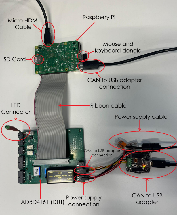
Connect the ADRD4161 (DUT) to the Raspberry Pi using the ribbon cable |
5 |
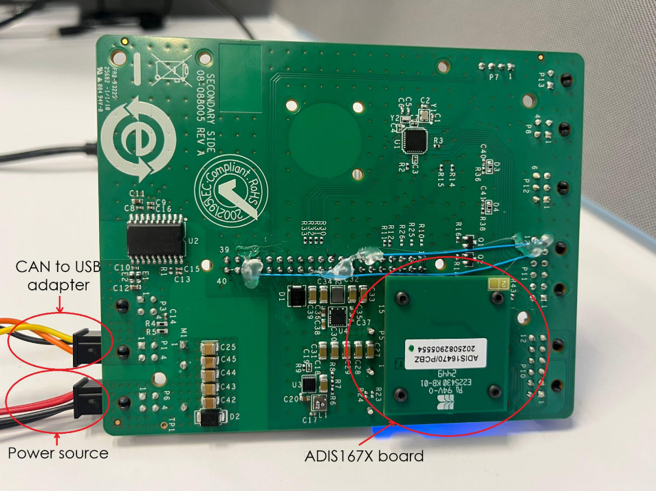
Connect the ADIS167X board on the back of the ADRD4161 (DUT) |
6 |
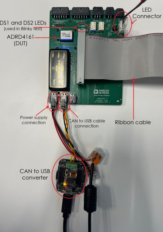
Connect the CAN to USB adapter to the ADRD4161 (DUT) and to the Raspberry Pi using the USB-A to USB-C cable |
7 |
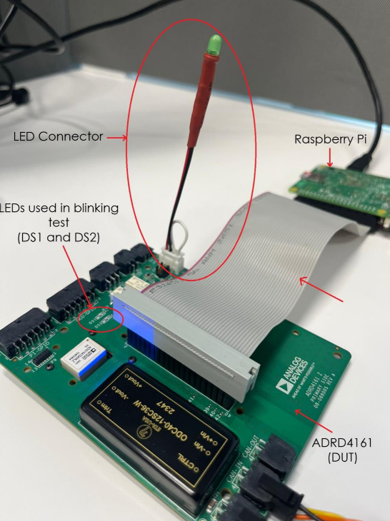
Connect the LED connector to the ADRD4161 (DUT) |
8 |
Connect the 12V power supply into the ADRD4161 (DUT) |
Test Process
Enabling Wifi
Before starting the testing procedure, make sure the Raspberry Pi is connected to Wifi.
After the RPi boots, press
CONTROL+Cto exit the test screen.Click on the Wifi network you want to connect to.
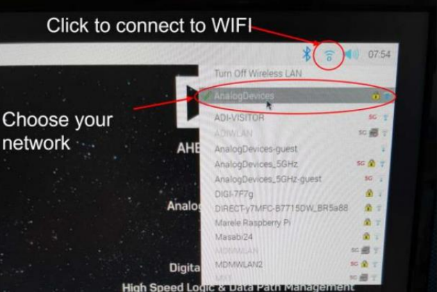
Type in the password. After successfully connected, reboot the Raspberry Pi by following the below instructions.
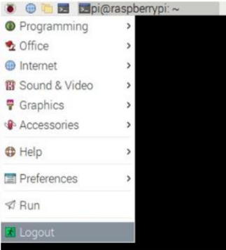
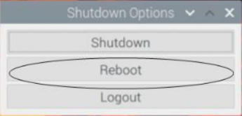
Running the Test Software
After the Raspberry Pi reboots, the test screen will appear on the monitor as shown below.
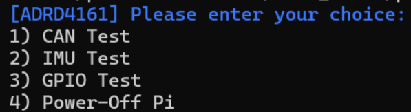
The following test menu should appear:
[ADRD4161] Please enter your choice:
1) CAN Test
2) IMU Test
3) GPIO Test
4) Power-Off Pi
1) CAN Test
Type “1” into the terminal and press ENTER to start the 1) CAN Test
test suite.
Make sure the CAN to USB adapter is connected to the ADRD4161 (DUT) and Raspberry Pi boards as shown in the system connections figure.
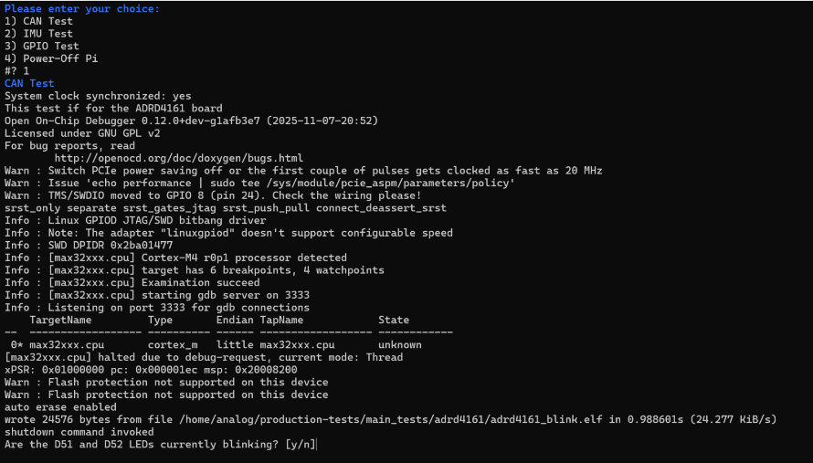
Visually check if the DS1 and DS2 LEDs are blinking. Type “y” if yes or “n” or not when prompted. You can see their position in the ADRD4161 connections and LED connector figures above.
Warning
If a “FAILED” message appears, check the USB connection to the CAN to USB adapter (found on port P7) and re-run the test for up to 3 times.
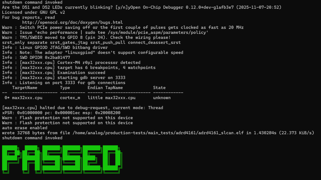
If the test runs with no failures, a green “PASSED” message will appear on the screen.
2) IMU Test
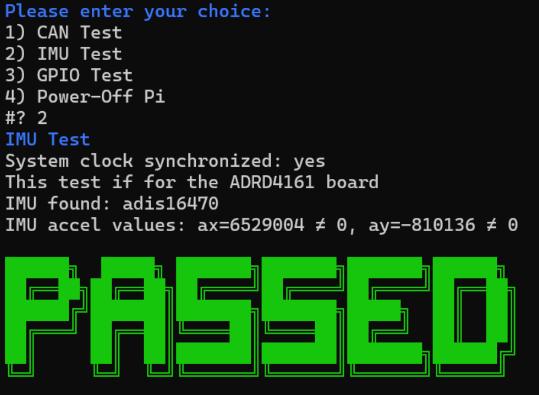
Type “2” into the terminal and press ENTER to start the 2) IMU Test.
Make sure the ADIS167X (IMU) board is properly connected to the ADRD4161 (DUT) board, as shown in the ADIS167X connection figure.
Warning
In case a failure occurs, a “FAILED” message appears. Check the presence of the ADIS167X board and its connections and re-run the test for up to 3 times.
If the second test runs with no failures, a green “PASSED” message will appear on the screen.
3) GPIO Test
Type “3” into the terminal and press ENTER to start the 3) GPIO Test.
Make sure the LED connector is connected to the ADRD4161 (DUT) board as shown in the LED connector figure.
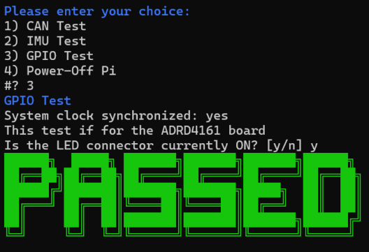
Visually check if the LED connector connected to the GPIO header is on. Type “y” if yes or “n” for no.
Warning
In case a failure occurs, a “FAILED” message appears. Check that the LED connector is properly connected and re-run the test for up to 3 times.
If the third test runs with no failures, a green “PASSED” message will appear on the screen.
Pass Criteria
After the tests 1), 2) and 3) have successfully passed, you can consider the DUT as being functional.
4) Power-Off Pi
Type “4” and press ENTER in the terminal to power off the RPi. Disconnect
the LED connector and CAN to USB adapter from the last tested DUT. Disconnect
the last tested DUT from the RPi by removing the ribbon cable.
Repeat the testing procedure for the next DUT.
Note
If at any point a test fails, you should retry the test suite for up to 3 times.