Production Testing
Overview
The production testing framework for ADRV9009-ZU11EG comprises Bash scripts operating on both a Raspberry Pi host and the device under test (DUT). Testing requires a Raspberry Pi 4 board (host) connected via Ethernet cable to the DUT with attached HDMI monitor and USB keyboard for GUI-based test selection and execution.
Test Duration
Step Description |
Estimated Time (minutes) |
|---|---|
Test bench setup |
5 min |
Software test |
10 min |
Total time |
15 min |
Test Requirements
Required Hardware
Computing and Display
1x Raspberry Pi 4 (USB 3.0 connection mandatory) + USB-C Power Supply
1x HDMI monitor
1x USB keyboard (connected to USB 2.0 black port)
Connectivity and Cables
1x CAT5 Ethernet cable (DUT M2 port connection)
1x USB A-to-USB Type-C cable (Raspberry Pi USB 3.0 to DUT)
1x USB A-to-Micro USB cable (Raspberry Pi USB 2.0 to DUT P8 UART)
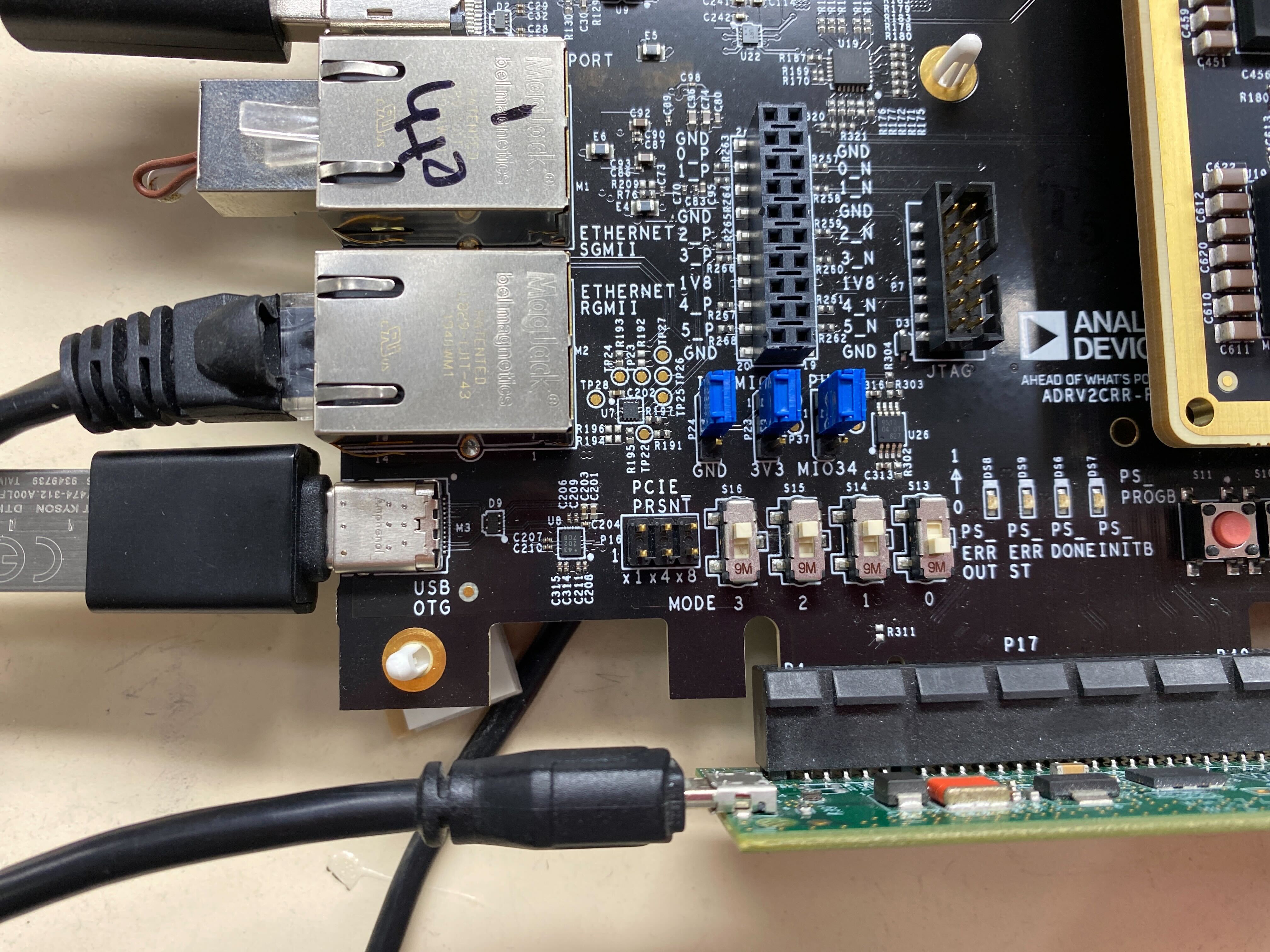
1x I2C programming cable (Raspberry Pi pins 3, 2, 6 to ADRV2CRR-FMC P19)
1x DisplayPort-to-HDMI cable (DUT P2 video output)
1x USB-C OTG cable (USB host mode testing)
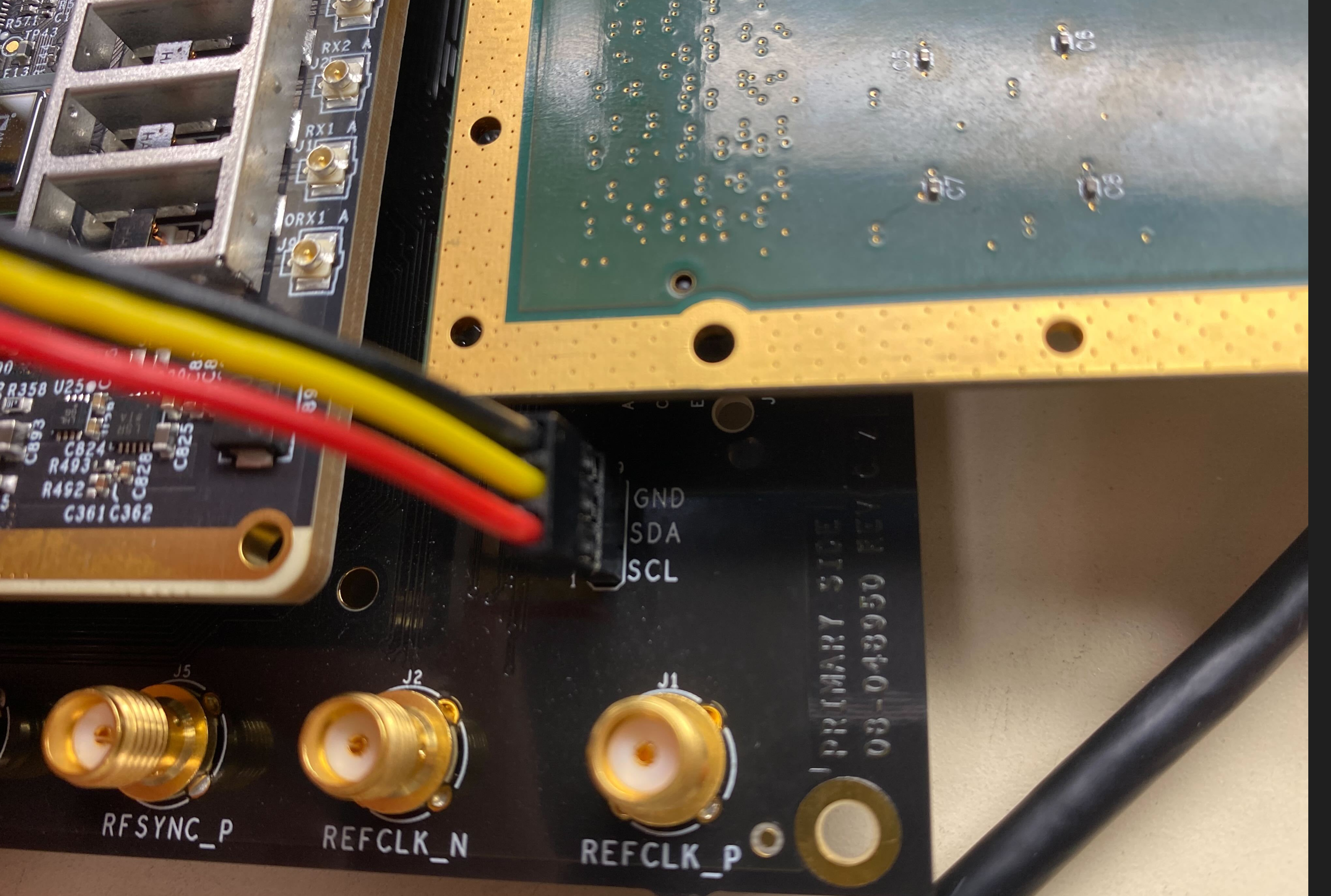
Figure 1 I2C connection between Raspberry Pi and ADRV2CRR-FMC
Storage
1x Raspberry Pi microSD card (minimum 8GB Class 10)
1x DUT SD card (minimum 8GB Class 10, inserted in P15)
1x USB 3.0 FAT-formatted memory stick
Test Equipment and Loopbacks
1x ADRV2CRR-FMC carrier board
1x ADRV9009-ZU11EG RF-SOM
1x QSFP loopback (P3, Molex 747630020)
1x SFP loopback (P4, Amphenol SF-SFPPLOOPBK-003.5)
1x FMC loopback (P1 on ADRV2CRR-FMC, iWave VITA)
1x PCIe loopback (P17, Whizz Systems, powered via USB micro)
1x Ethernet loopback (M1 SGMII port)
1x Audio loopback (P6 and P5 connectors)
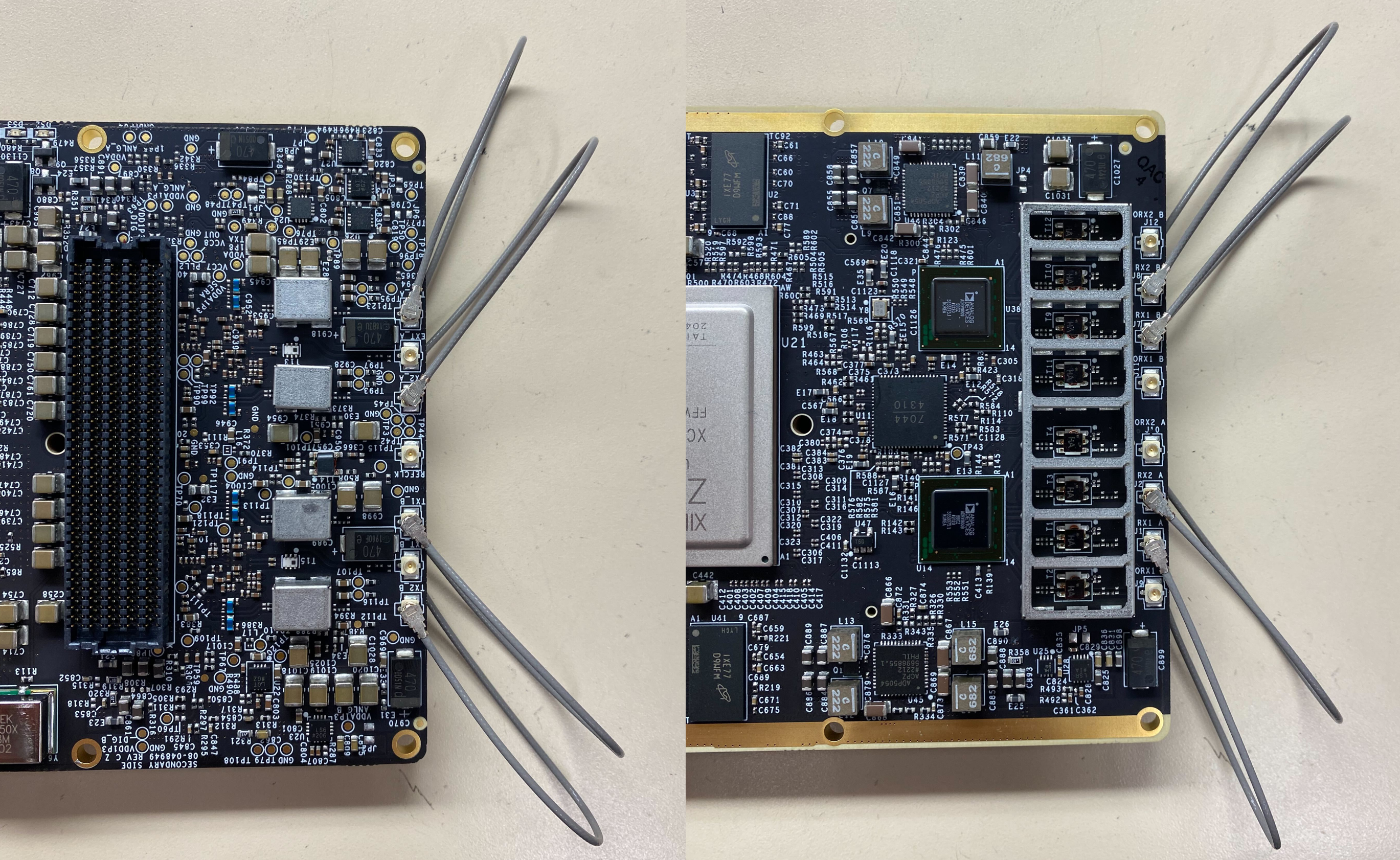
4x U.FL loopback cables (RF testing: U.FL-2LPHF6-068N1T-A-100)
Power
1x USB-C power supply (Raspberry Pi)
1x 12V power supply (DUT P11)
Required Software
ADRV9009-ZU11EG SD Card Image
Latest release (15 December 2022):
File:
talise_prod_15dec_2022.zipChecksum:
b056120a53e13b197b5b366742d9f5c7Source: Zynq official release
Raspberry Pi SD Card Image
Latest release (15 December 2022):
File:
rpi_talise+prod_15dec.zipChecksum:
0d8759784c1cebbcd908fe8a01083272Based on Raspbian with desktop; includes testing scripts
Required Setup
No. |
Steps |
|---|---|
1 |
Connect HDMI cable to Raspberry Pi |
2 |
Attach USB keyboard to Raspberry Pi |
3 |
Insert Raspberry Pi microSD card |
4 |
Supply power to Raspberry Pi |
5 |
Connect all loopbacks to DUT:
|
6 |
Connect Ethernet cable between Raspberry Pi and DUT (M2 port) |
7 |
Connect USB cables:
|
8 |
Connect I2C pins (Raspberry Pi to P19) |
9 |
Insert SD card into DUT (P15) |
10 |
Connect DisplayPort cable to DUT (P2) |
11 |
Power on DUT using 12V power supply (P11) |
Test Process
Initialization
Power on both DUT and Raspberry Pi
Verify boot screen appears on monitor
Label RF shielding top cover with serial number and MAC address
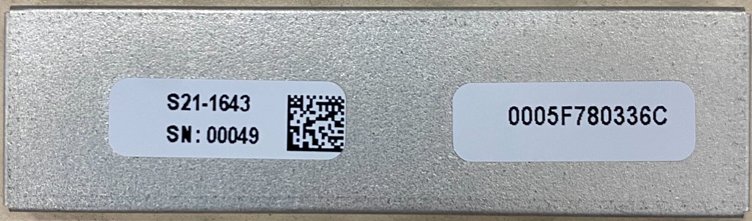
Warning
Do not swap RF shielding covers between boards after labeling.
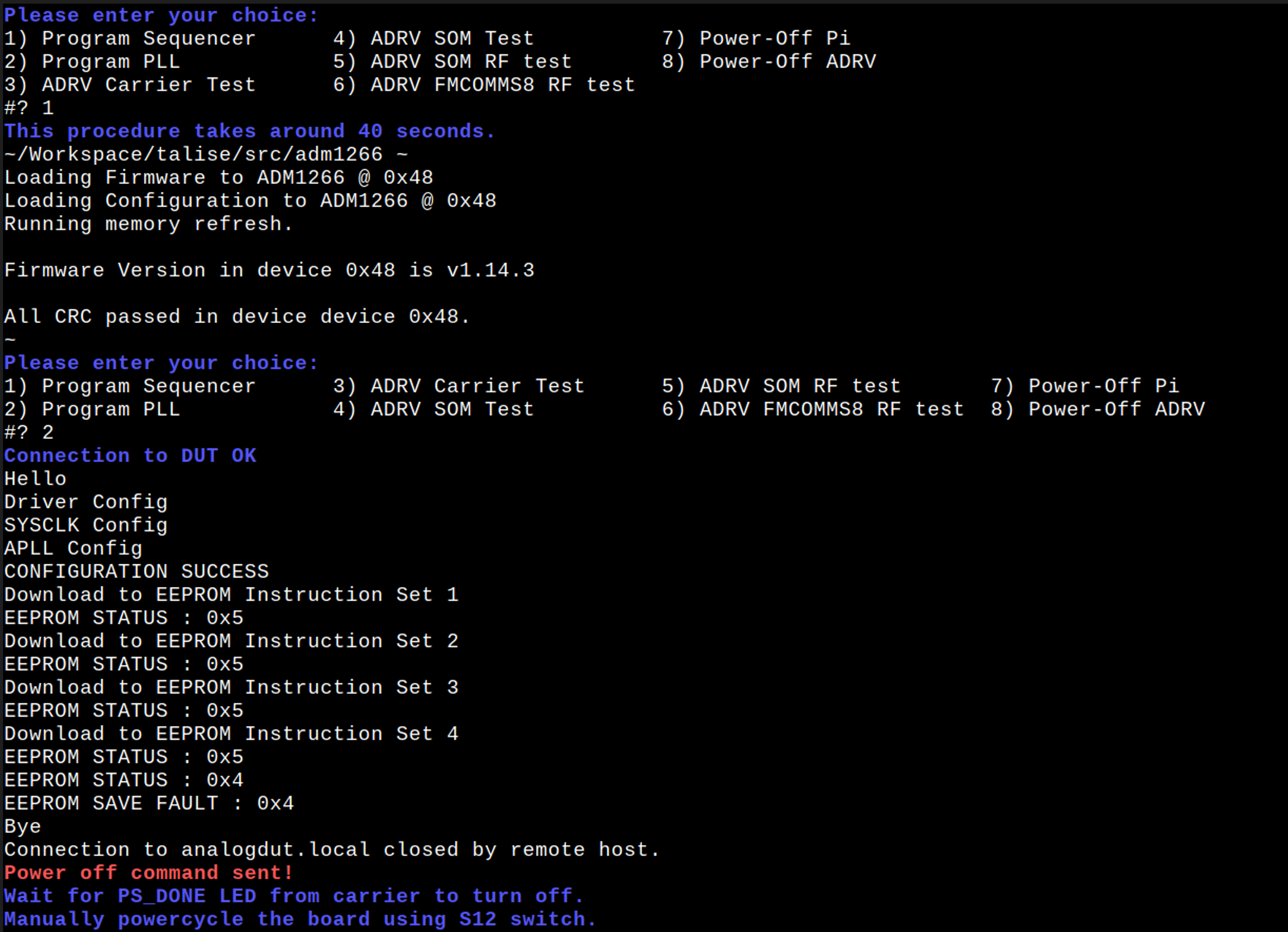
Running the Test Software
After the Raspberry Pi boots up, the test menu will appear on the monitor.

Execute the following tests in order:
Test 1
Test 2
Test 4
Test 5
Test 6
Note
Testing begins by checking Ethernet connectivity. If an error message appears, verify the following:
Ethernet cable is properly connected
DUT is powered on
SD card is inserted correctly
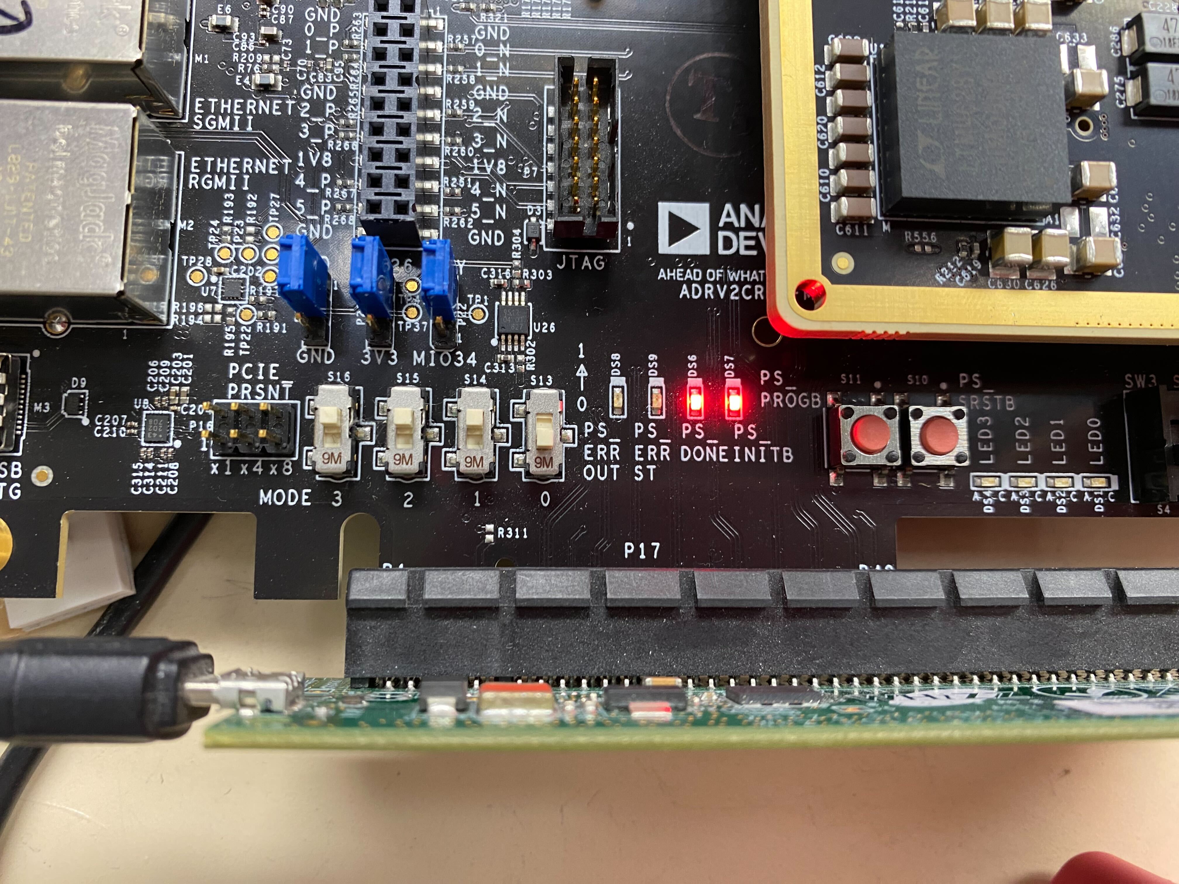
Boot mode switches (S13-S16) are configured for SD boot

Test 1
Wait 30 seconds after PS_DONE LED illuminates before proceeding.
Test 2
Power cycle is required after PS_DONE LED turns off.
Test 4, 5, and 6
Follow on-screen instructions.
Note
Test 5 requires entering the last four digits of the MAC address from the RF shielding label.
Heatsink Installation
After completing the initial tests, install the heatsink and rerun Test 6.
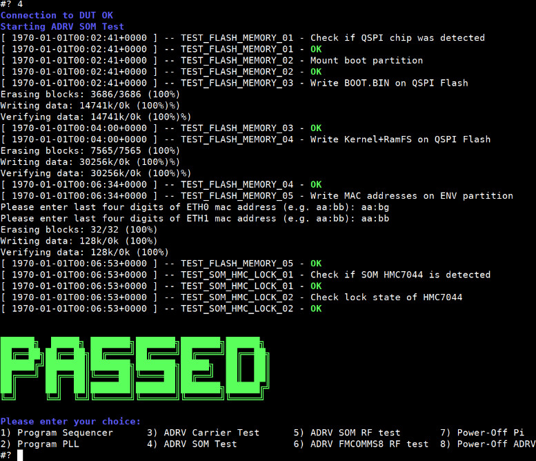
Pass Criteria
A green “PASSED” message displayed indicates that the DUT passed all assigned tests.
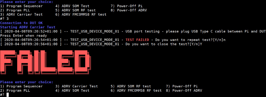
Fail Criteria
A “FAIL” message will be displayed if any test fails. The system will prompt whether to repeat the test immediately.
Note
You may repeat failed tests indefinitely
You can bypass a failed test (not recommended) by responding “NO” to “Do you want to close the test?” question
Shutdown Procedure
No. |
Steps |
|---|---|
1 |
Select menu item 8 to power off ADRV |
2 |
Wait until LEDs DS6 and DS7 turn off |
3 |
Disconnect power from ADRV |
4 |
Select menu item 7 to power off Raspberry Pi |
5 |
Unplug power (prevents SD card corruption) |
Warning
Always follow the proper shutdown procedure to prevent SD card corruption.