Hardware Assembly
Complete guide for assembling the X-Band phased array development platform with proper connections and mounting procedures.
Overview
The X-Band platform assembly involves connecting multiple high-frequency components that require careful handling and proper mounting techniques to ensure optimal performance. This guide provides step-by-step instructions for assembling the complete system from unboxing to power-on.
Warning
Before You Begin: Ensure you have reviewed all safety precautions and have proper ESD protection in place. The components are sensitive to static discharge and physical damage.
Required Components
Kit Contents
Verify you have received all components before beginning assembly:
Primary Evaluation Boards
ZCU102 Evaluation Board - Xilinx Zynq UltraScale+ MPSoC development platform
AD9081-FMCA-EBZ - AD9081 MxFE (Mixed-Signal Front End) evaluation board
ADXUD1AEBZ - X/C Band Up/Down Converter evaluation board
ADAR1000EVAL1Z - X/Ku-Band Beamforming evaluation boards
Cables and Interconnects
FMC-HPC Extension Cable - High Pin Count FMC interconnect
SMA-to-SMPM RF Cables - Various lengths for RF signal connections
USB Micro-B Cable - For UART/JTAG connections to ZCU102
Ethernet Cable (CAT5e or better) - For network connectivity
Power Cables - Barrel connector DC power cables
Power Supplies
12V DC Power Supplies - 12V (for ZCU102, ADXUD1A, and ADAR1000EVAL1Z)
Additional Hardware
microSD Card - Pre-loaded with Kuiper Linux image (16GB minimum)
Mounting Hardware - Standoffs, screws, spacers (if provided)
Tools Required
Essential Tools
#2 Phillips screwdriver - For mounting screws
Small flathead screwdriver - For jumper settings
ESD wrist strap and mat - For static protection
Digital multimeter - For voltage verification
Recommended Tools
Torque wrench for SMA connectors - 8 in-lbs recommended
Cable ties and clips - For cable management
Oscilloscope - For signal verification
Pre-Assembly Preparation
Safety Precautions
Warning
ESD Sensitivity: All boards contain ESD-sensitive components. Always use proper grounding and anti-static precautions.
a. Set up ESD-safe workspace
Use anti-static mat connected to earth ground
Wear anti-static wrist strap connected to ground
Store boards in anti-static bags when not in use
Humidity should be 40-60% to minimize static
b. Inspect all components
Check for physical damage during shipping
Verify all connectors are clean and undamaged
Ensure no bent pins on FMC or other connectors
Verify power supplies output correct voltages
Assembly Procedure
Step 1: ZCU102 Base Preparation
1.1 Initial Board Setup
a. Place ZCU102 on stable surface
Ensure adequate clearance around all sides (minimum 2 inches)
Provide access to all connectors and switches
Keep board on anti-static mat
b. Verify power supply before connection:
Measure DC output: 12V ± 0.5V
Check polarity: Center pin positive
Minimum current rating: 6A
c. Do NOT connect power yet - complete all mechanical assembly first
1.2 FMC Connector Inspection
a. Inspect ZCU102 FMC-HPC connector:
Check for bent or damaged pins
Verify connector is clean and free of debris
Ensure retention clips are functional
Look for any signs of previous damage
Warning
Critical: The FMC connector has 400 pins. A single bent pin can damage both boards. Inspect carefully before mating.
1.3 FMC Extension Cable Connection (HPC0)
Important
Connect the FMC extension cable to ZCU102 HPC0 now, before installing the AD9081 riser board in the next step. The riser may obstruct access to HPC0 once seated.
a. Locate HPC0 on the ZCU102 (separate from HPC1 where the AD9081 will mount) b. Inspect HPC0 connector for bent or damaged pins c. Seat the FMC extension cable into HPC0 with even pressure until fully engaged d. Verify cable routing — ensure the free end can reach the Interposer board position without strain
Step 2: AD9081-FMCA-EBZ to ZCU102 Connection
2.1 FMC Board Preparation
a. Remove AD9081-FMCA-EBZ from anti-static bag
b. Inspect FMC connector on AD9081 board for damage
c. Check component orientation:
AD9081 IC should be toward the center of ZCU102 when installed
Board silk screen will indicate “Top” side
FMC keying ensures correct orientation
2.2 Attach Inline RF Filters
Important
Install the inline RF filters directly onto the AD9081 SMA connectors before mounting the board into the system. Access to these connectors is significantly harder once the board is seated on the ZCU102.
Screw the Mini-Circuits inline filters onto the AD9081 SMA connectors hand-tight, then snug with a torque wrench to 8 in-lbs:
TX Filters (VLF-5500+) — attach to DAC outputs:
AD9081 Connector |
Filter |
|---|---|
DAC0 (TX1) |
VLF-5500+ |
DAC1 (TX2) |
VLF-5500+ |
DAC2 (TX3) |
VLF-5500+ |
DAC3 (TX4) |
VLF-5500+ |
RX Filters (VLF-8400+) — attach to ADC inputs:
AD9081 Connector |
Filter |
|---|---|
ADC0 (RX1) |
VLF-8400+ |
ADC1 (RX2) |
VLF-8400+ |
ADC2 (RX3) |
VLF-8400+ |
ADC3 (RX4) |
VLF-8400+ |
Tip
Label the free end of each filter with a small cable tag (e.g., “TX1”, “RX2”) to make the XUD1A connections easier once the board is installed.
2.3 Mechanical Installation
a. Align AD9081-FMCA-EBZ with ZCU102 FMC-HPC1 connector:
Hold board parallel to ZCU102
Align FMC connector carefully - look for keying notch
Do not force - connector should align naturally
b. Carefully seat the FMC connector:
Apply even pressure on both ends of board
Press down firmly but gently
You should feel a positive “click” when fully seated
Board should be parallel to ZCU102 surface
c. Secure with mounting hardware:
Install 4 standoffs at mounting holes (if provided)
Use appropriate length standoffs (typically 10-15mm)
Hand-tighten screws - do not over-torque
Verify board is mechanically stable with gentle pressure
Note
Some configurations may not include standoffs. The FMC connector provides mechanical support, but standoffs improve stability and prevent board flex.
2.4 Visual Verification
Check gap between boards - should be uniform (~10mm)
Verify no bent components from installation pressure
Confirm FMC connector fully seated - no visible gap
Check board alignment - AD9081 board should be parallel to ZCU102
Step 3: ADXUD1AEBZ Up/Down Converter & Interposer Installation
3.1 Interposer to FMC Extension Cable
a. Connect the Interposer card to the free end of the FMC extension cable (already seated into ZCU102 HPC0 in Step 1.3)
Align the FMC connector carefully — check keying notch
Apply even pressure until fully engaged
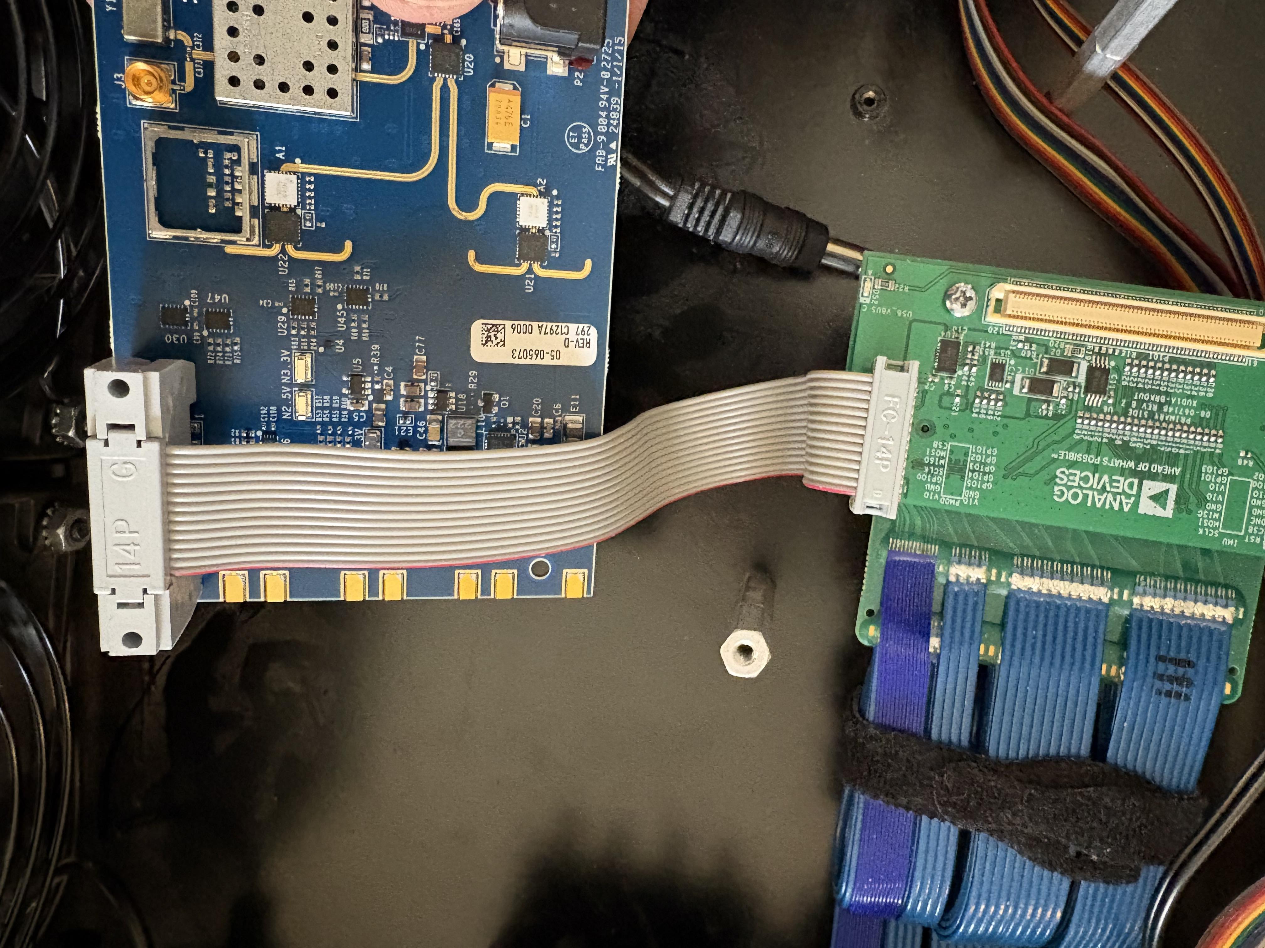
3.2 Connect Interposer PMOD to XUD1A
a. Connect the Interposer PMOD to the PMOD connector on the underside of the ADXUD1AEBZ:
The Interposer PMOD is pin-compatible with the XUD1A PMOD, enabling a direct connection
The 14-Pin PMOD 6 Inch Cable is optional but recommended — it allows the XUD1A to be positioned further from the Interposer for easier RF cable routing
3.3 Mechanical Mounting
a. Position the ADXUD1AEBZ in the system enclosure/tray
b. Fasten the board down to standoffs:
Use appropriate standoff height to allow clearance for the PMOD cable on the underside
Hand-tighten screws — do not over-torque
Verify the board is mechanically stable
3.4 Clock Connections
Select the appropriate step based on your clock config:
Connect a 100 MHz external reference signal to J3 on the underside of the ADXUD1AEBZ board.
Signal level: 0 dBm typical
No action required. The on-board 100 MHz VCXO will be used automatically.
Connect the external LO signal to the SMA-F connector on the side of the ADXUD1AEBZ board.
3.5 RF Power Splitter/Combiner Connections
a. Connect 4x power splitter/combiners to the SMA-F connectors on the end of the ADXUD1AEBZ:
One splitter per TX/RX channel pair
Hand-tighten, then torque to 8 in-lbs
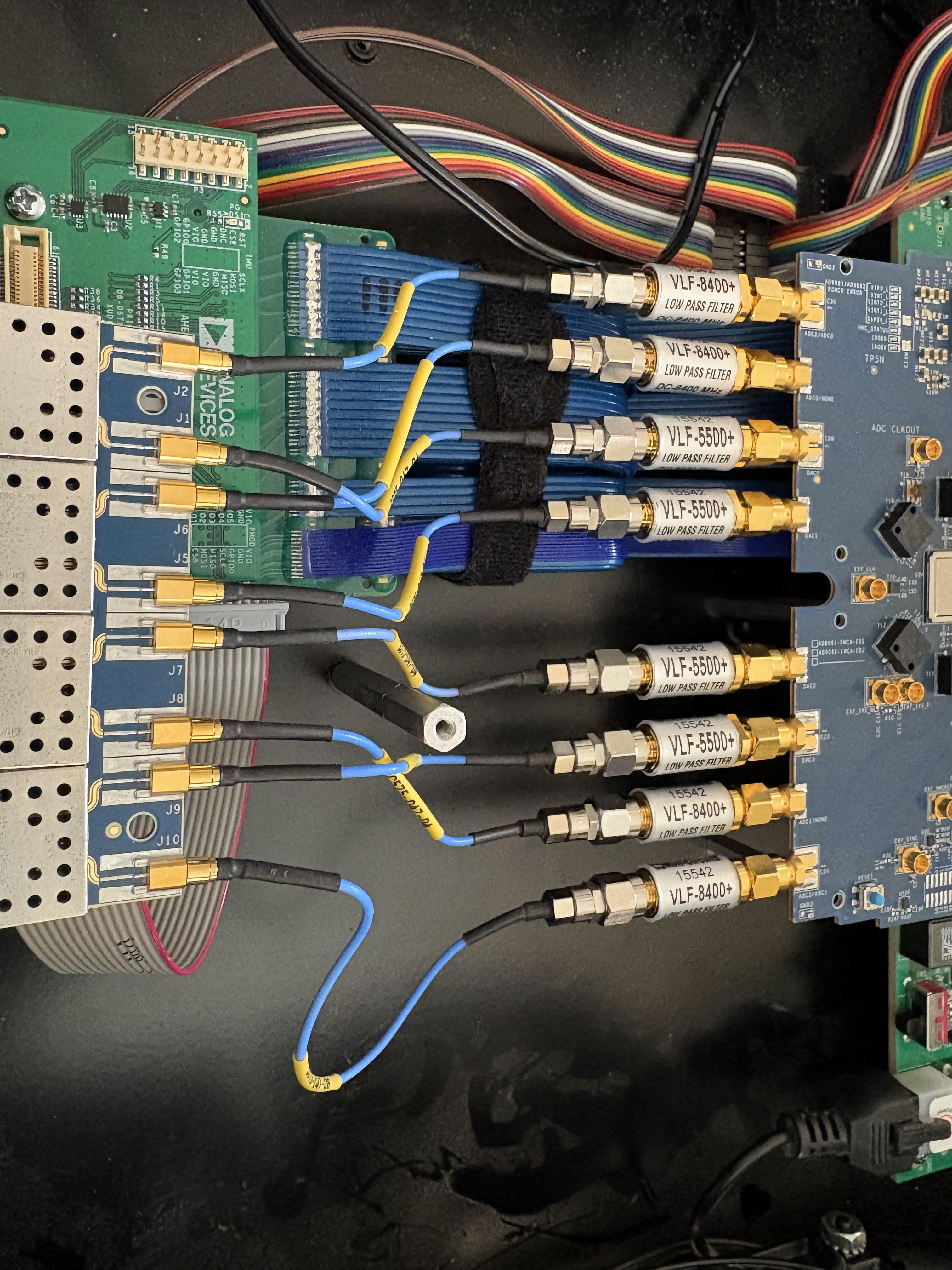
3.6 AD9081 → Filter → XUD1A RF Connections
Note
Filters are optional. If not using inline filters, connect SMA cables directly from the AD9081 DAC/ADC connectors to the corresponding XUD1A ports. The filter column can be skipped entirely.
Connect SMA cables from the free end of each inline filter (installed in Step 2.2) to the corresponding XUD1A port. If no filters are installed, connect directly from AD9081 to XUD1A:
TX Path — AD9081 DAC outputs → (optional VLF-5500+) → XUD1A input:
AD9081 Connector |
Filter (optional) |
XUD1A Port |
|---|---|---|
DAC0 (TX1) |
VLF-5500+ |
J1 |
DAC1 (TX2) |
VLF-5500+ |
J5 |
DAC2 (TX3) |
VLF-5500+ |
J7 |
DAC3 (TX4) |
VLF-5500+ |
J9 |
RX Path — XUD1A output → (optional VLF-8400+) → AD9081 ADC input:
AD9081 Connector |
Filter (optional) |
XUD1A Port |
|---|---|---|
ADC0 (RX1) |
VLF-8400+ |
J6 |
ADC1 (RX2) |
VLF-8400+ |
J8 |
ADC2 (RX3) |
VLF-8400+ |
J2 |
ADC3 (RX4) |
VLF-8400+ |
J10 |
Warning
RF Connector Torque: Torque all SMA connections to 8 in-lbs. Over-tightening damages connectors; under-tightening causes poor RF performance.
Step 4: Heatsink and ADAR1000 Connections
4.1 Heatsink attach
a. Apply absorber pads to ADTR1107s - The thermal resistance of the ICs prevents thermal padding/paste from being effective, direct contact with heatsink is sufficient
b. Attach heatsink and evenly torque down hex screws
4.2 ADAR1000 Board Connections
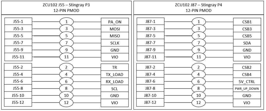
a. Connect PMODs from ZCU102 to Stingray
ZCU102 J55 → Stingray P3
ZCU102 J87 → Stingray P4
Important
PMOD Cable Orientation: If the cable is oriented correctly it will not damage the hardware — it is safe to test multiple orientations. You will know the orientation is wrong when you boot the system and no yellow LED appears on the Stingray board. Simply power down, flip the cable, and retry.
4.3 RF Distribution Network
RF Distribution (from ADXUD1AEBZ to ADAR1000s):
a. Connect Splitter I/O to each ADAR1000:
Each splitter corresponds to a subarray (2 ADAR1000s)
Use equal-length cables for phase matching (6-12 inches, matched to ±2mm)
Label each cable with board destination
Verify all connections are secure
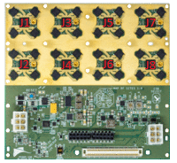
RF Connector Mapping Reference
Connection # |
XUD1A Connector |
Stingray Connectors |
|---|---|---|
1 |
J1D (SMA) |
J1, J3 (SMPM) |
2 |
J1C (SMA) |
J2, J4 (SMPM) |
3 |
J1B (SMA) |
J6, J8 (SMPM) |
4 |
J1A (SMA) |
J5, J7 (SMPM) |
4.4 Antenna Connection
a. Connect antenna tiles to ADAR1000 SMPM outputs:
Use SMPM bullets to mate
Ensure each SMPM bullet is properly seated
Step 5: Power Connections
Warning
Power Supply Sequence: Connect power cables but do NOT apply power until all connections are complete and verified.
5.1 ZCU102 Power
a. Locate power connector J52 on ZCU102 b. Verify power supply output: 12V ± 0.5V
5.2 AD9081-FMCA-EBZ Power
a. Power is supplied through FMC connector HPC1 to ZCU102 board
5.3 ADXUD1AEBZ Power
a. Connect 12V power supply:
Locate power connector on ADXUD1AEBZ
Connect 12V power supply
Verify polarity (typically center positive)
Do not apply power yet
5.4 ADAR1000 Board Power
a. For one ADAR1000 board:
Connect 12V power supply to P2
b. For multiple ADAR1000 boards: - Use single 12V power supply and daisy chain power between boards using P1 Board 1 → P2 Board 2