User guide
The complete user guide of the evaluation board can be found at REV C USER GUIDE.
Hardware guide
Hardware Versions
Tip
Note that we are only shipping REV C boards as of now. Please click on the link to the REV C user guide for this board in the section below. Rev A information is only here for legacy purposes.
REV C (Current)
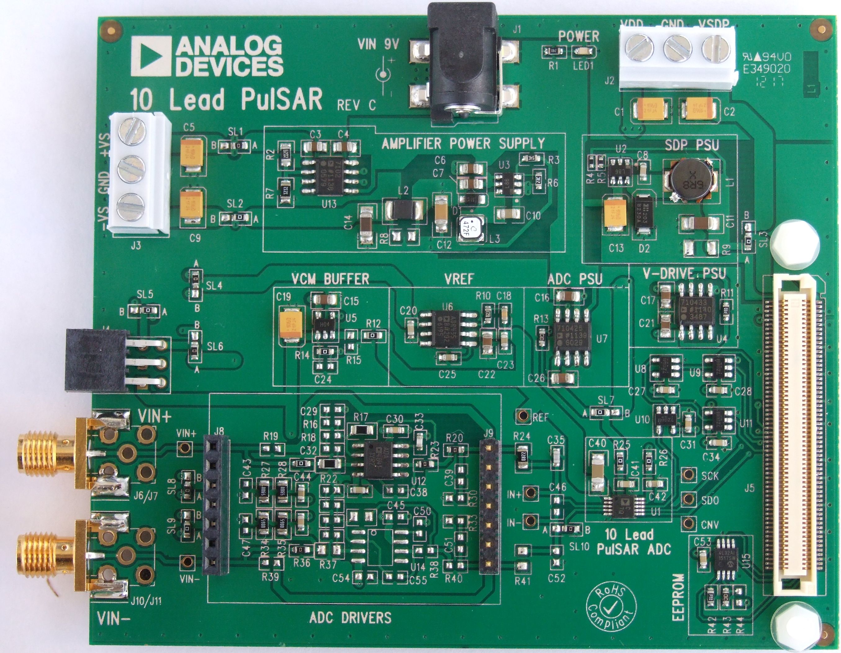
The REV C board is the current board that is available for purchase. This board contains the on-board power supplies to power all portions of the board - the ADC, Reference, Amplifiers and SDP board. This board operates from a simple +9V wall adaptor which is included as part of the evaluation board kit. This board interfaces to the SDP controller board.
All documentation for this version of hardware is contained in the REV C USER GUIDE.
PMOD Compatible
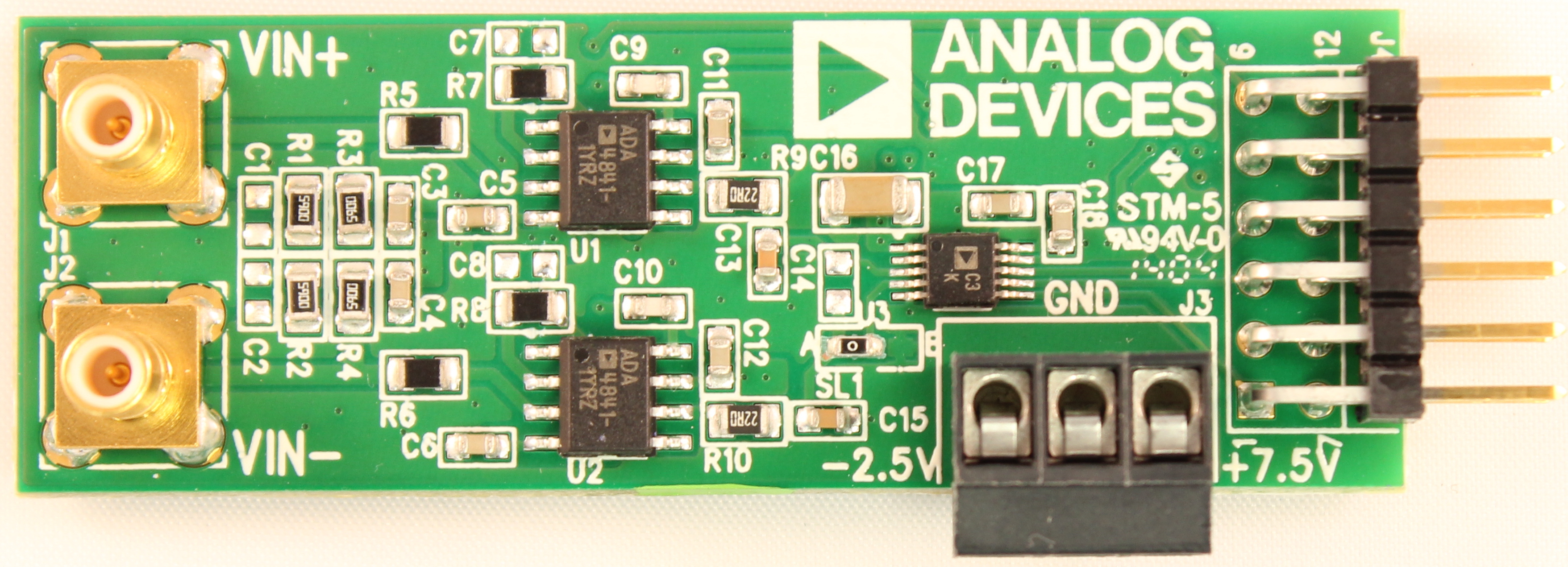
PMOD compatible hardware is a very simple board which plugs directly into microprocessor and FPGA boards which have PMOD peripherals.
Complete details about the PulSAR ADC PMOD boards can be found by visiting our PulSAR ADC PMOD Page.
SOFTWARE NOTE: If using the PMOD compatible version of the hardware, please install this version of the software from the EVAL-ADAQ40xx product page.
HARDWARE NOTE: If using the PMOD compatible version of the hardware, you will need to use the PMOD to SDP interposer board to fully evaluate the system. This PMOD to SDP interposer board can be used to connect any of the 10 PulSAR PMOD compatible boards to the PC or laptop. All detailed user information along with schematic, bill of materials, and layout files for this board can be found at the EVAL-ADAQ40xx product page.
REV A (Legacy)
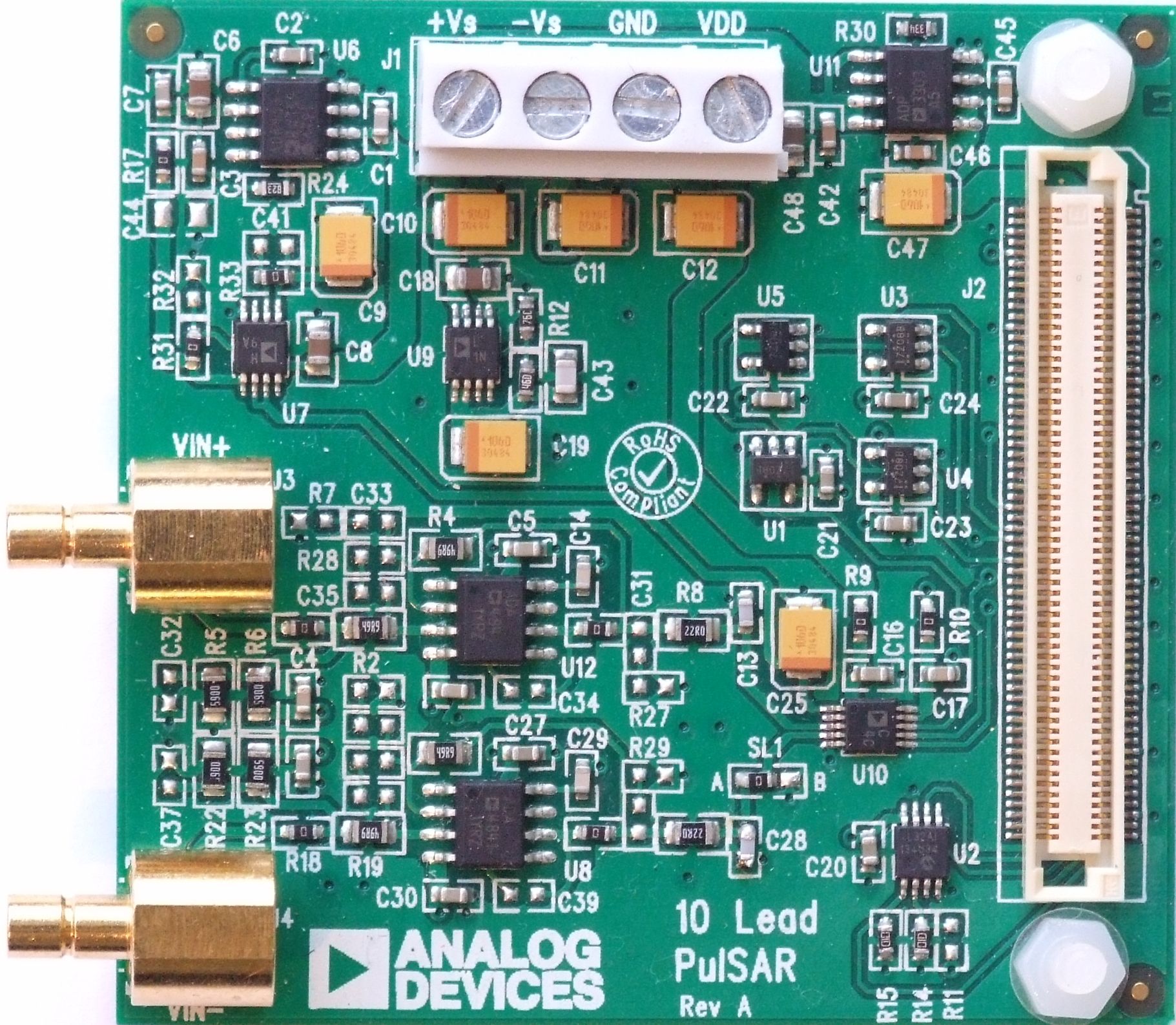
REV A hardware is a very simple board which requires power supply rails from a bench-top power supply to power the board. This board interfaces to the SDP controller board. This board is no longer available to purchase and is shown here for legacy purposes.
Important
All detail which follows in this section applies to REV A hardware.
General Description
For a complete list of supported devices, see Pulsar ADC.
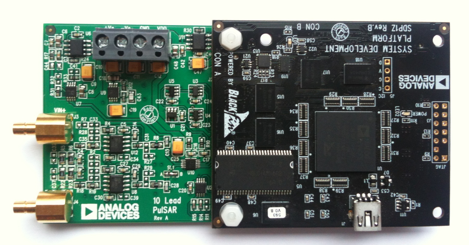
On-board components include a high precision buffered band gap 5.0V reference (ADR435), reference buffers (AD8032), a signal conditioning circuit with two op-amps (ADA4841-1) and regulators to derive necessary voltage levels on board (ADP3334, ADP3303). This evaluation board interfaces to the SDP board via a 120 pin connector. SMB connectors, J3 and J4, are provided for the low noise analog signal source.
Power Supplies
The evaluation board requires power from an external bench top supply, applied to J1 connector.
Table 1. External Power Supply Required (max 12V across +Vs to -Vs)
Power Supply |
Voltage Range |
Purpose |
|---|---|---|
+Vs |
+7.5V |
Supplies ADR435, regulator ADP3334 which supplies +7V to +Vs of ADA4841-1, regulator ADP3303 which supplies +5V to SDP |
-Vs |
-2V |
Amplifier ADA4841-1 negative rail |
Vdd |
2.5V |
ADC Supply Rail for following ADCs AD7980, AD7982, AD7983, AD7984, AD7988-5 |
5V |
ADC Supply Rail for following ADCs AD7685, AD7686, AD7687, AD7688, AD7690, AD7691, AD7693, AD7694, AD7942, AD7946 |
On board regulators generate required levels from the applied +Vs rail. The regulators used are the ADP3334 (U9) which supplies +7V for the +Vs of the ADC driver amplifier (ADA4841), while the ADP3303-5 delivers 5V to the SDP board connector, J2 to power the SDP board. The SDP in turn provides a 3.3V V_DRIVE which supplies the IOVDD of the ADC in addition to the logic gates (U1, U3, U4). Each supply is decoupled where it enters the board and again at each device. A single ground plane is used on this board to minimize the effect of high frequency noise interference.
Reference
An external 5V reference (ADR435 U6) is used to supply the ADCs. This reference is buffered by the AD8032.
Serial Interface
The evaluation board uses the SPORT interface from the SDP BF527 DSP. A number of AND gates are used to clock and gate the SPORT transfer to the ADC device. See U1, U3, U4.
Solder Links
There is one 3 Solder Link Option on the board. It is configured depending on which generic of ADC is on the specific evaluation board as described below.
Table 2. Solder Link Default Setting
Analog Inputs
The analog inputs to the evaluation board are J3 and J4 SMB (push on) connectors. These inputs are buffered with dedicated amplifier circuitry (U8 and U12) and discrete as shown in the schematic. The circuit allows for different configurations, input range scaling, filtering, addition of a DC component, use of different op-amp and supplies. The analog input amplifiers are set as unity gain buffers at the factory.
The default configuration sets both U8 and U12 at mid-scale generated from a buffered reference voltage divider (VCM). The evaluation board is factory configured for providing either a single ended path or a fully differential path as described in Table 2.
Software guide
Windows Evaluation Software (SDP)
The evaluation board software is available to download from the product webpage.
Tip
The software install is a two part install, user should proceed through both parts prior to connecting board for first time.
Install the software prior to connecting the SDP board to the USB port of the PC. This ensures that the SDP board is recognized when it connects to the PC.
Start the Windows operating system and insert CD.
The installation software should launch automatically. If it does not, run the setup.exe file from the CD.
After installation is completed, power-up the EVAL board as described in Power Supplies section.
Plug the evaluation board into the SDP board and the SDP board into the PC using the USB cable included in the box.
When the software detects the EVAL board, proceed through any dialog boxes that appear to finalize the installation.
The default location for the software is
C:\Program Files\Analog Devices\10 Lead PulSAR ADCs.
This location contains the executable software, datasheets and example files.
Install Steps
Proceed through the install allowing the software and drivers to be placed in the appropriate locations. Only after the software and drivers have been installed should you connect the SDP board to the PC. There are two portions to the software install.
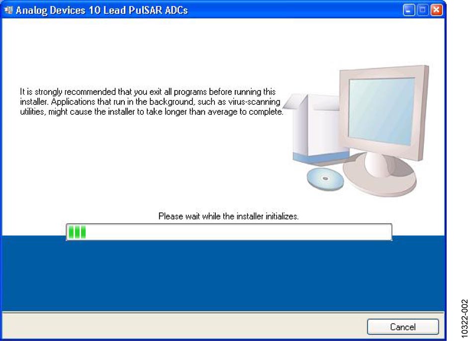
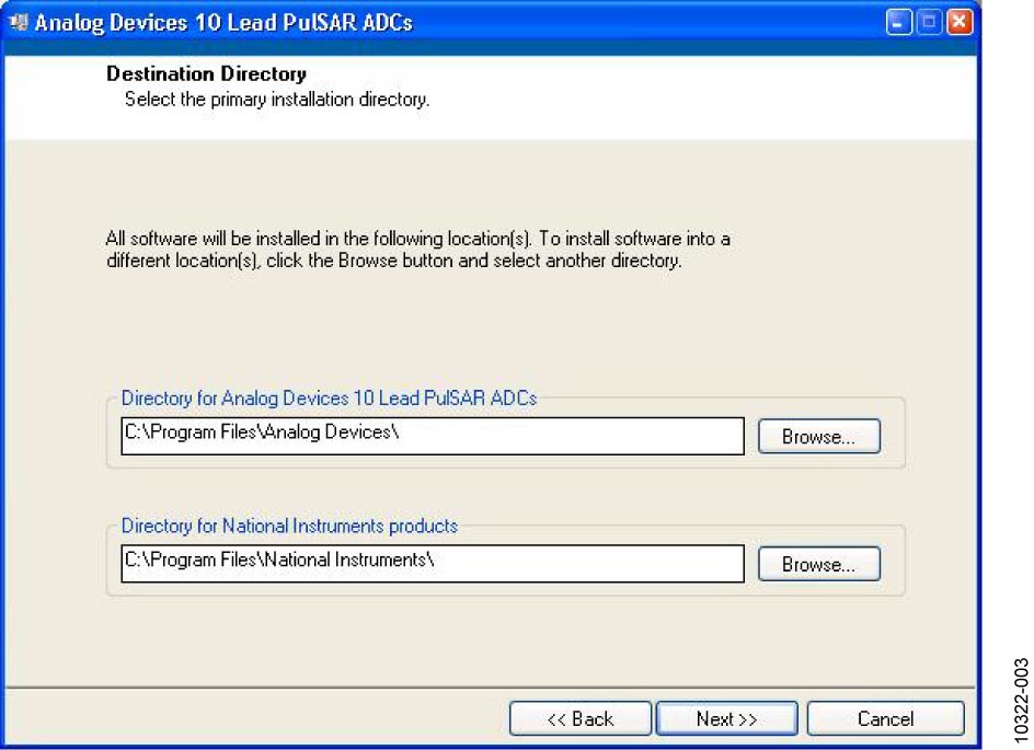
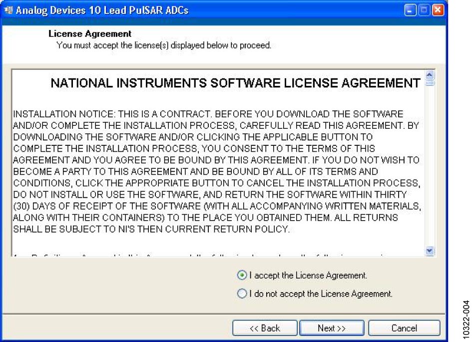
Figure 3 Accept National Instruments Software License Agreement
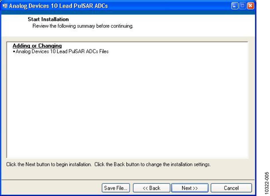
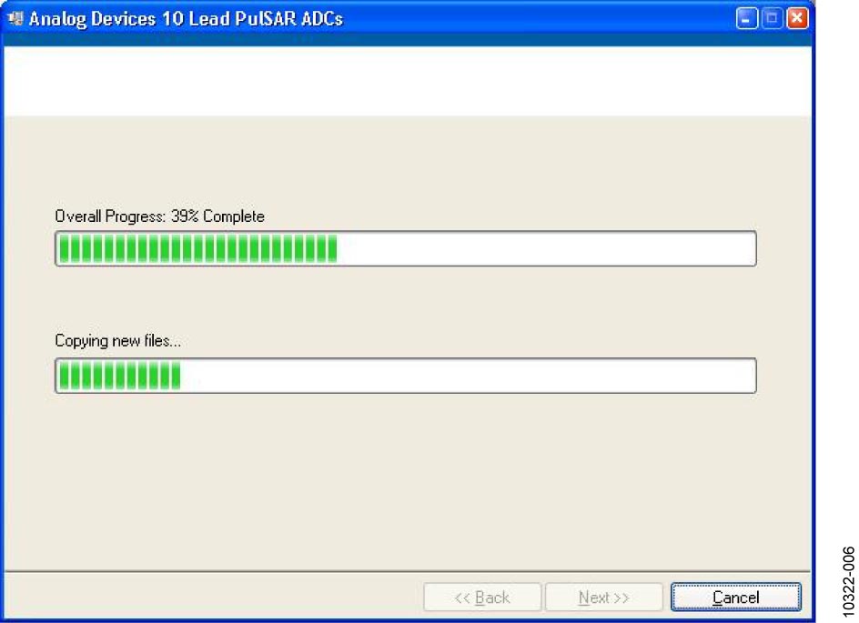
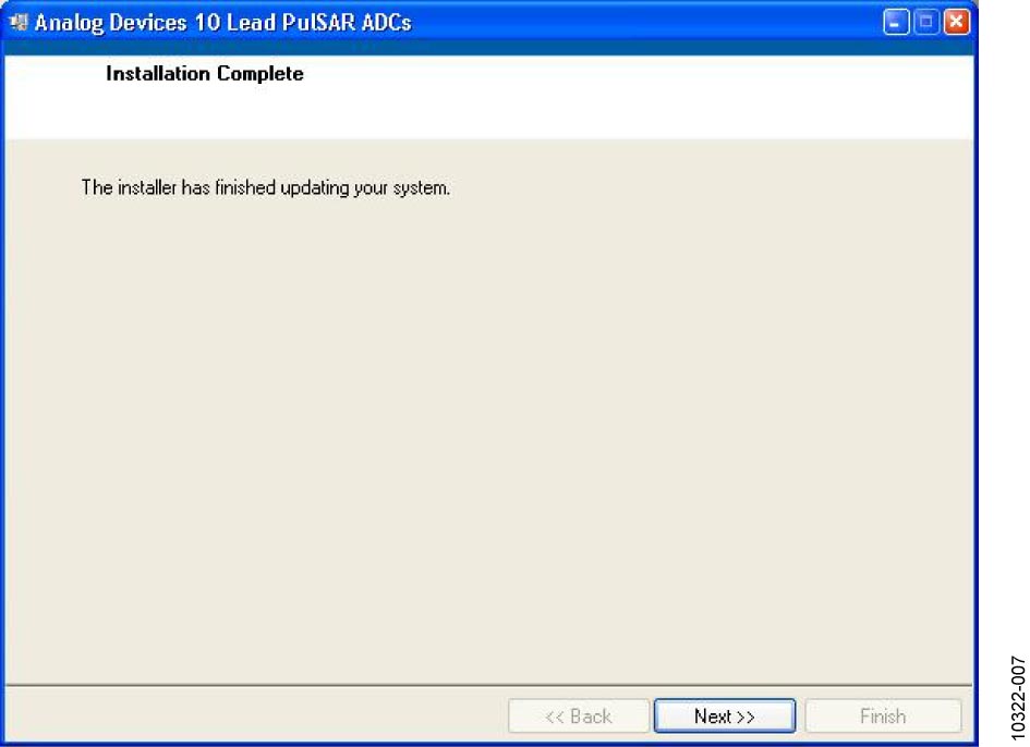
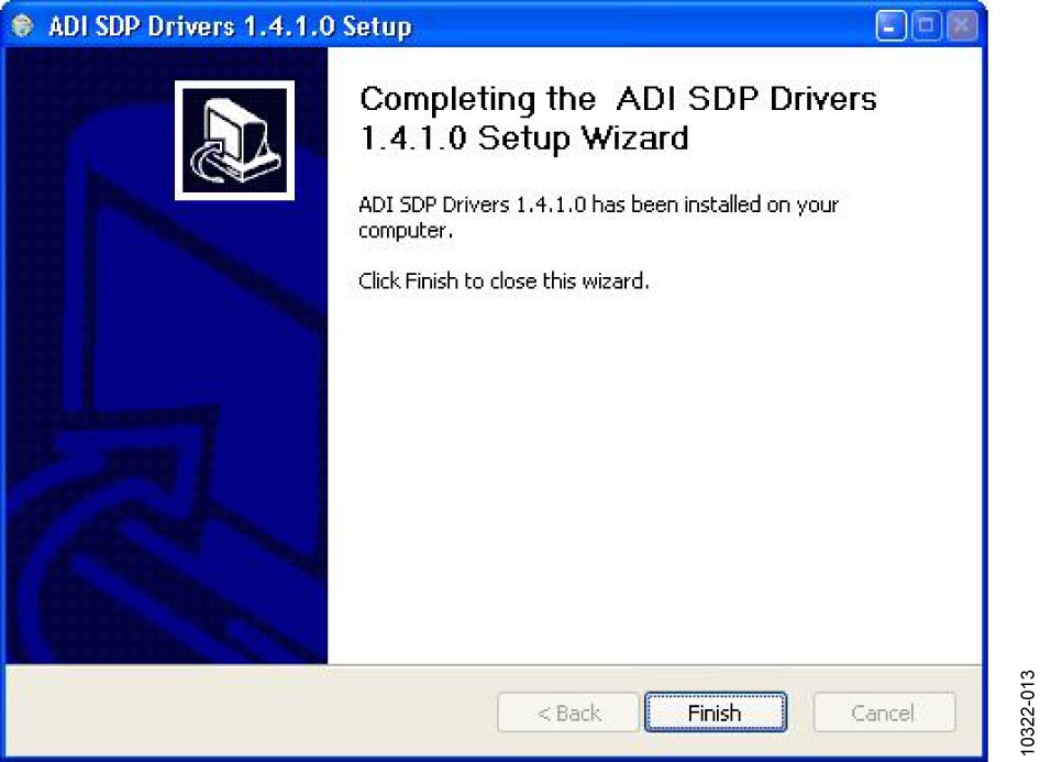
Figure 6 Installation Complete, Click Next to Complete and Finish
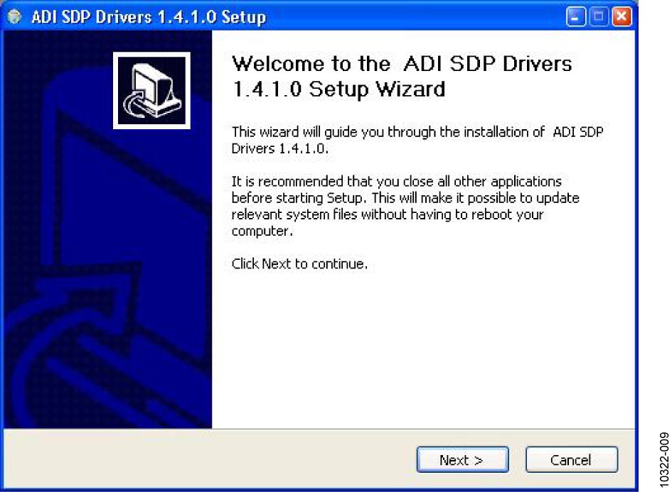
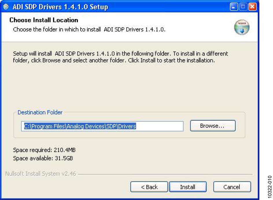
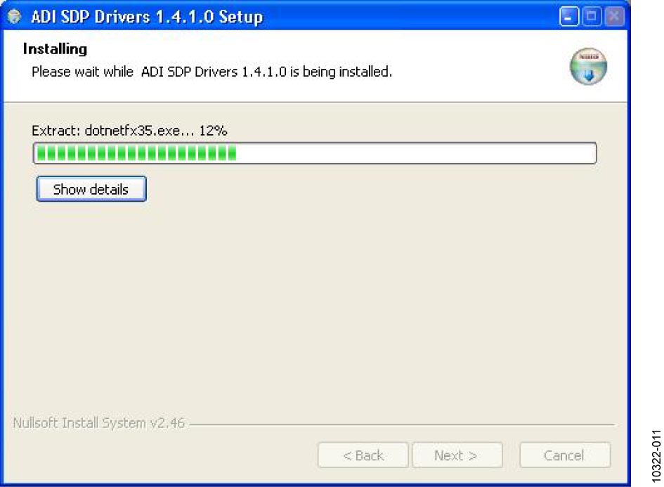
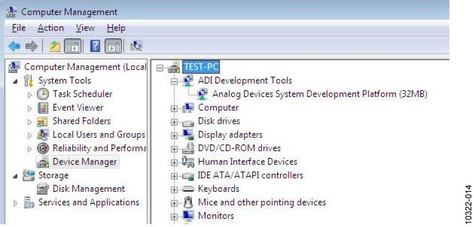
The second part of the software installation is the drivers related to the SDP board. These must be installed for the evaluation board to function correctly.

When you first plug in the SDP board via the USB cable provided, allow the new Found Hardware Wizard to run. You can check that the drivers and the board are connected correctly by looking at the Device Manager of the PC. The Analog Devices System Development Platform (32MB) should appear under ADI Development Tools.
Board Operation
Connect SDP controller board to the evaluation board with the J2 connector (screw into place as required). The software is configured to find the evaluation board on either connector of the SDP board.
Power board with appropriate supply as described.
Connect to PC with USB cable provided.
Launch software. Click Start > All Programs > Analog Devices > 10 Lead PulSAR ADCs.
Apply signal source and capture data.
Running the software with hardware connected
To run the program, do the following:
Click Start > All Programs > Analog Devices > 10 Lead PulSAR ADCs. To uninstall the program, click Start > Control Panel > Add or Remove Programs > 10 Lead PulSAR ADCs.
If the SDP board is not connected to the USB port when the software is launched, a connectivity error is displayed.
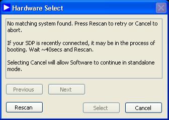
Simply connect the EVAL board to the USB port of the PC, wait a few seconds, click Rescan, and follow the instructions.
The software connects to the board and displays the following:
Once the board has been correctly detected, the software panel will open. The example below shows the AD7691 panel.
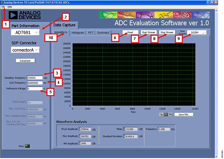
Description of User Panel
File menu with choice of: Load Data, Save Data as .tsv, Save Picture, Print, Exit.
Part detection: When hardware is connected to the USB port, the software automatically detects which generic is connected and displays it. Without hardware, the software can be operated in standalone mode for data analysis.
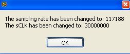
Sampling Frequency: The default sampling frequency will match the maximum sample rate of the ADC connected to the board. The user can adjust the sampling frequency; however, the sample frequency must be an integer divider of the SCLK frequency.
SCLK Frequency: The default SCLK frequency is set to 60 MHz, which is the maximum allowable from the SDP. Nominal values for correct operation are 60 MHz, 30 MHz, and 20 MHz.
External reference voltage: By default, this reference is 5V (ADR435 on board reference). If user changes the reference voltage, then they should change this input accordingly.
Read: to perform a single capture.
Start: to perform a continuous capture from the ADC.
Stop: to stop streaming data.
Number of samples: Select the number of samples to analyse; when running continuously, this number will be limited to 65536 samples.
Data tabs: Waveform, Histogram, FFT, Summary.
Linux Software (FPGA Carriers)
The PulSAR ADC evaluation boards are supported with the following Linux drivers depending on the carrier/connector variant:
PMOD variant (CoraZ7S): PulSAR ADC Linux driver (ad_pulsar.c)
FMC variant (ZedBoard): AD400x Linux driver (ad4000.c)
No-OS Software
The No-OS driver and project for PulSAR ADC can be found at: