EVAL-AD7195-ASDZ Hardware Guide
Set-up Procedures
After following the instructions in the Software Procedures section, set up the evaluation and SDP boards as detailed in this section.
Warning
The evaluation software and drivers must be installed before connecting the EVAL-AD7195-ASDZ evaluation board and EVAL-SDP-CB1Z board to the USB port of the PC to ensure the PC correctly recognizes the evaluation system.
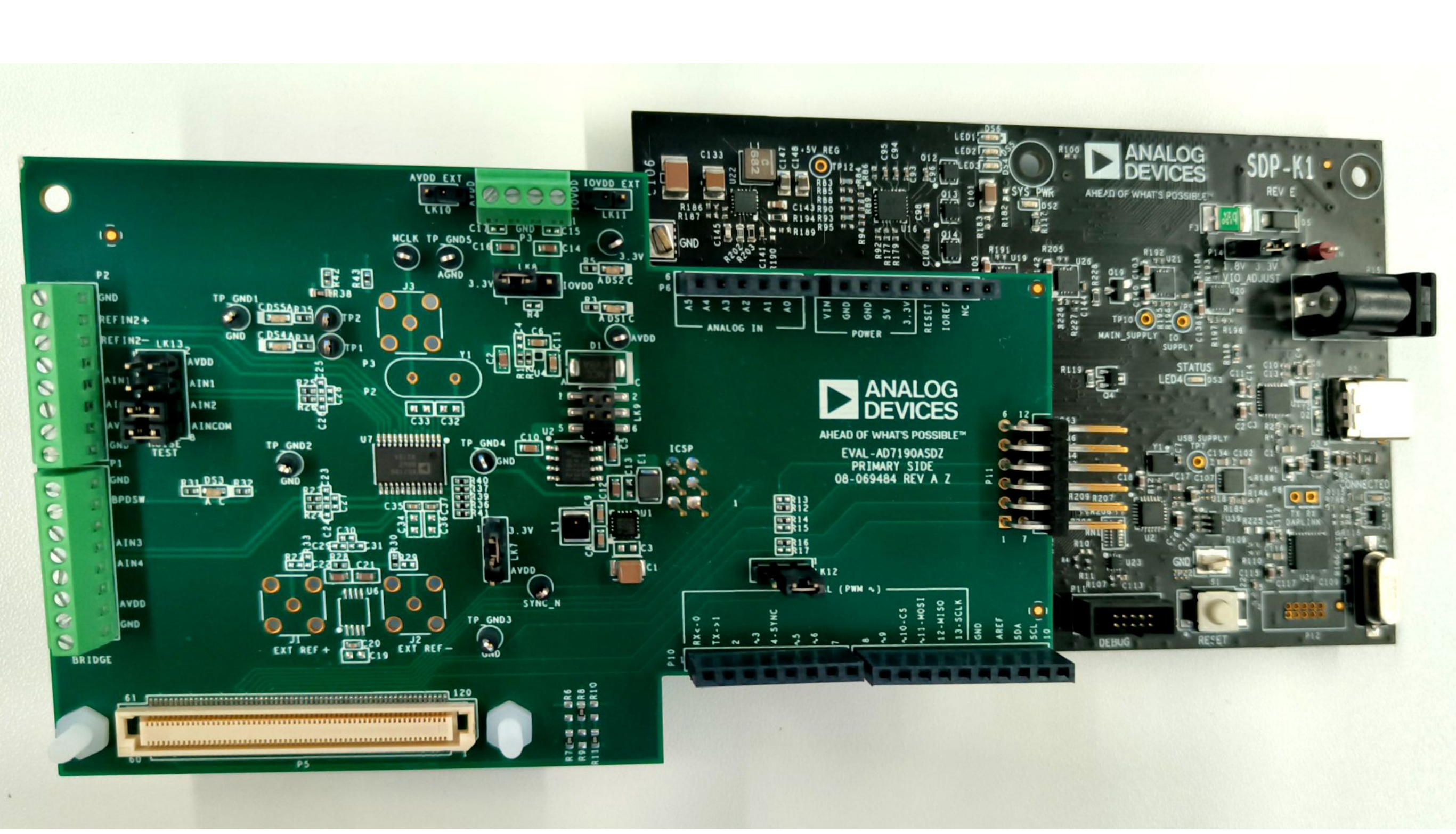
Connect the EVAL-AD7195-ASDZ to the controller board
Option A: Connect the EVAL-AD7195-ASDZ to the EVAL-SDP-CK1Z
Using the 120 pin connector
Screw the two boards together using the plastic screw-washer set included in the evaluation board kit to ensure that the boards are connected firmly together.
Using the Arduino Connectors
Option B: Connect the EVAL-AD7195-ASDZ to the EVAL-SDP-CB1Z
Using the 120 pin connector
Screw the two boards together using the plastic screw-washer set included in the evaluation board kit to ensure that the boards are connected firmly together.
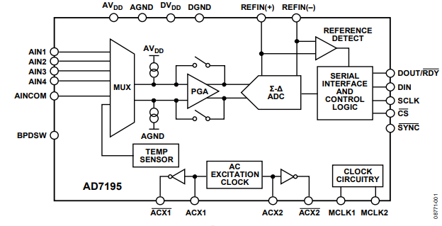
Block Diagram
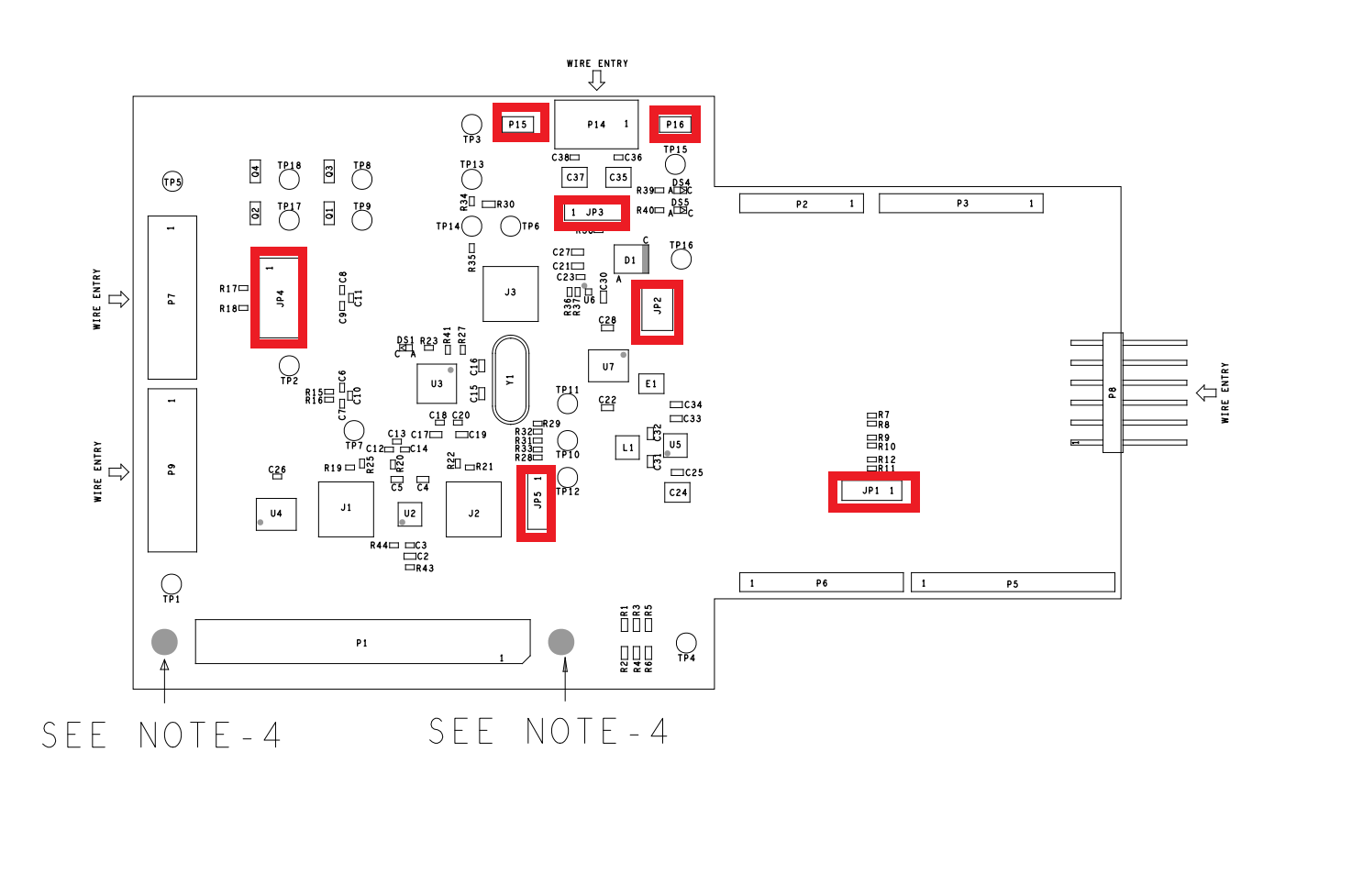
Hardware Link Options
Link Numbers |
Colour |
Default Position |
Description |
|---|---|---|---|
JP1 |
Black |
A |
Used for stacking of Eval boards. To select Eval board(CS_N): Pos A(1-2): selects eval board 1 (CS_ARD_1) Pos B(2-3): selects eval board 2 (CS_ARD_2) |
JP2 |
Black |
C |
AVDD voltage select: Pos A: sets AVDD to 3.3v LDO supply Pos B: sets AVDD to external source Pos C: sets AVDD to 5V LDO Supply |
JP3 |
Black |
A |
IOVDD voltage select: Pos A: sets IOVDD to 3.3v LDO supply Pos B: sets IOVDD to external source |
JP4 |
Black |
Uninserted |
This link shorts AIN1 to AIN2. This is useful to perform noise tests on the AD7195 |
JP5 |
Black |
A |
DVDD voltage select: Pos A: DVDD is connected to 3.3V Pos B: DVDD is connected to AVDD |
P15 |
Black |
Uninserted |
Used as external AVDD voltage connector for scp boards |
P16 |
Black |
Uninserted |
Used as external IOVDD voltage connector for scp boards |
On Board Connections
Bridge Connections
Connector P9: DC (Analog Input)
Functionality:
Bridge Connection
Connection |
Function |
|---|---|
1 |
Ground/Sheild |
2 |
Excitation+ |
3 |
External Reference + |
4 |
AIN 3 with DC filtering |
5 |
AIN 4 with DC filtering |
6 |
External Reference - |
7 |
BPDSW |
8 |
Excitation- |
Link JP4: Low Noise Test Circuitry
Functionality:
Low Noise Test
-ALL INSERTED
Connection |
Function |
|---|---|
1-2 |
AVDD |
3-4 |
AIN1 |
5-6 |
AIN2 |
7-8 |
AINCOM |
External Powers
Connector |
Function |
|---|---|
P14 Pin 1-2 |
External IOVDD connection |
P14 Pin 3-4 |
External AVDD connection |
P15 |
External AVDD connection for SCP Boards |
P16 |
External IOVDD connection for SCP Boards |
Digital Connectors
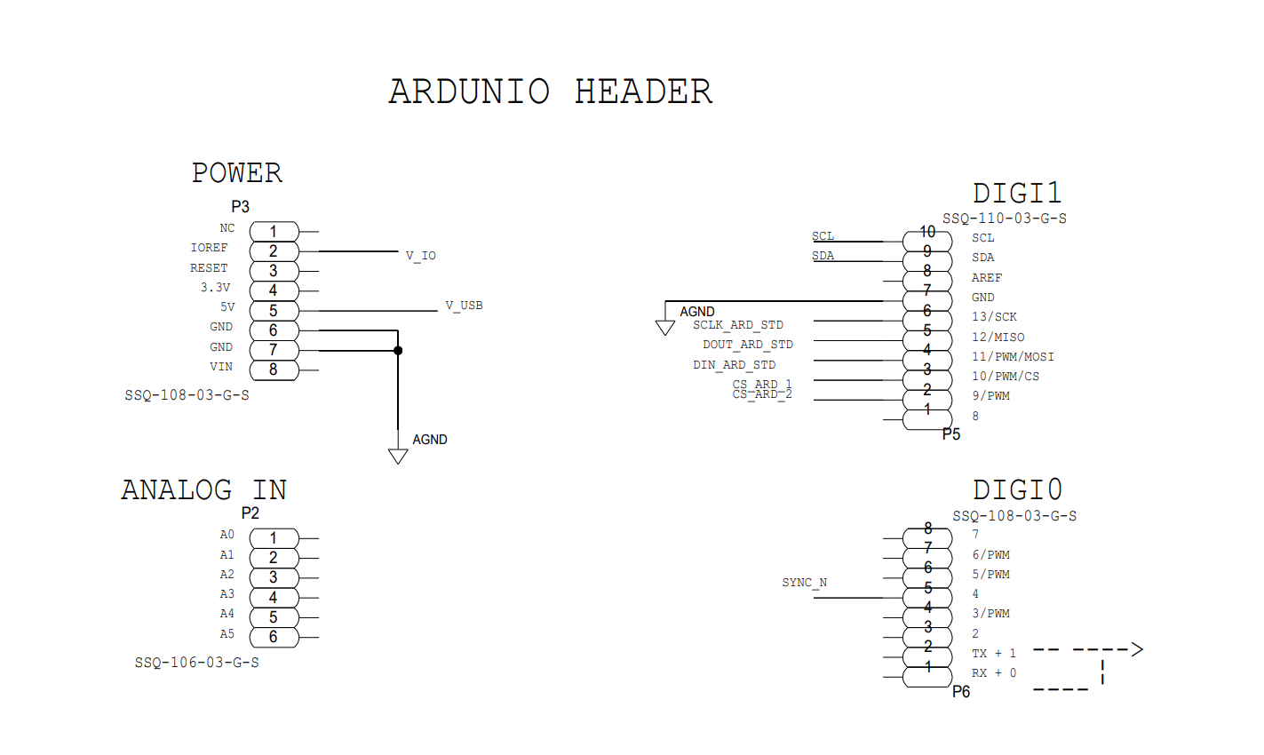
SDP 120 Pin Connector P1 |
Function |
Arduino connector P2,P3,P5,P6 |
|---|---|---|
3,4 |
GND |
P3-6,P3-7 |
5 |
V_USB |
P3-5 |
6,11,17,23,28,36,40,46,52 |
GND |
P5-7 |
56 |
EEPROM_A0 |
|
58,63,69,75 |
GND |
|
78 |
SYNC_IN |
P6-5 |
79 |
SCL |
P6-10 |
80 |
SDA |
P6-9 |
81 |
GND |
|
82 |
SCLK |
P6-6 |
83 |
SDO/miso |
P6-5 |
84 |
SDI/mosi |
P6-4 |
85 |
CS_N |
P5-3,P5-2 |
86,93,98,109,115 |
GND |
|
116 |
VIO |
P3-2 |
117,118 |
GND |
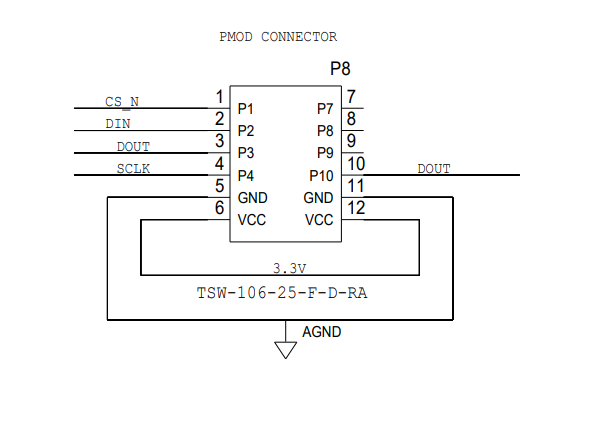
Pmod Connector P8
Connection |
Function |
Connection |
Function |
|---|---|---|---|
1 |
CS_N |
7 |
|
2 |
DIN |
8 |
|
3 |
DOUT |
9 |
|
4 |
SCLK |
10 |
|
5 |
GND |
11 |
GND |
6 |
IOVDD |
12 |
IOVDD |
SMB Connections
There are 3 SMB connections on the board. To allow clock signals and reference into the board.
J1 Provides option for External Reference+
J2 Provides option for External Reference-
J3 Brings external MCLK to the AD7195
Power Supplies
The evaluation board receives power through the controller board when connected to the PC via USB. Linear regulators generate the required power supply levels from the applied USB voltage.
AVDD (JP2) selection
DVDD (JP5) selection
3.3V supply (DEFAULT)
3.3V supplies DVDD
AVDD
AVDD connected to DVDD
IOVDD (JP3) selection
3.3V supply (DEFAULT)
3.3V regulator supplies IOVDD ADP150
External IOVDD
Connections on Connector P14
V_IO from SDP
R38 to be mounted
Serial Interface
There are four primary signals: CS, SCLK, SDI, and SDO/RDY (all are inputs, except for SDO/RDY, which is an output).
Serial communication options
SDP-B board and the respective 120 pin SDP connector.
When using the SDP-B connection (120 pin) The evaluation board connects via the serial peripheral interface (SPI) to the Blackfin® ADSP-BF527 on the SDP-B board.
Arduino connection SDP-K1
Pmod connector
Standalone mode
Reference Options
DEFAULT ADR4525 On Board external reference on REFIN1+
LTC6655LN-2.5/LTC6655LN-4.096 On Board external reference on REFIN+
Option to use ultra low noise reference
External Reference on REFIN1+ Connector J1
AVDD as Reference via R25
Design and Integration Files
Schematics, layout files, and bill of materials are available on the EVAL-AD7195ASDZ product page.