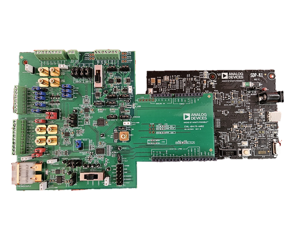
AD4170-4 on SDP-K1 (EVAL-SDP-CK1Z)
The AD4170-4 evaluation board can be controlled and evaluated using the EVAL-SDP-CK1Z (SDP-K1) System Demonstration Platform controller board with a USB-C connection to a Windows PC running the ACE Plugin software.
Overview
The EVAL-SDP-CK1Z (SDP-K1) is a modern system demonstration platform featuring:
USB-C connector for simplified connectivity
Full ACE plugin support
Arduino-compatible connectors for evaluation board attachment
Compact form factor
Universal driver support across Windows versions
Hardware Setup
Board Connection
Critical Warning: The evaluation software and drivers must be installed BEFORE connecting both the EVAL-AD4170-4ARDZ evaluation board and the EVAL-SDP-CK1Z controller board to the PC USB port. This ensures the evaluation system is correctly recognized by Windows.
Connection Procedure:
Install all software first (see Software Installation section below)
Do not connect the SDP-K1 to USB yet - complete installation first
Connect the EVAL-AD4170-4ARDZ to the EVAL-SDP-CK1Z using Arduino connectors
Verify default link/jumper positions on the evaluation board (see Hardware Guide section of User Guide)
Connect USB-C cable to the EVAL-SDP-CK1Z board (after software installation)
Allow Windows to detect and install drivers if needed
Launch ACE Plugin software to begin evaluation
Power and Connectivity
Power Supply:
The SDP-K1 is powered via USB-C connector
Most standard USB 3.0/3.1 ports provide sufficient power
Use a quality USB cable to ensure stable connection
No additional external power supply is required
USB Connection:
Use the provided USB-C cable
Supports USB 2.0 minimum (compatible with USB 3.0+ ports)
Maintains backward compatibility with older USB hosts if adapter used
Typical data communication rate: 12 Mbps (full-speed USB)
Software Installation and Configuration
Prerequisites
Before installing software, you need:
Windows 7 or later operating system
Administrator privileges on the PC
Minimum 500 MB free disk space
USB 2.0 or higher port available
Internet connection (for downloading software)
Required Software Components
Install in this order:
ACE Software (Base platform)
SDP Controller Drivers (Universal for all SDP boards)
AD4170 Plugin (Device-specific plugin)http://beta-tools.analog.com/virtualeval/
Software Download Locations:
Step 1: Install ACE Software
Download ACEInstall.exe to a temporary folder on your PC
Double-click ACEInstall.exe to begin installation
The program requests administrator permissions
Click “Yes” when the User Account Control (UAC) dialog appears
Default installation path:
C:\Program Files (x86)\Analog Devices\ACE
Follow the ACE Setup Wizard:
Step 1.1: Welcome Screen
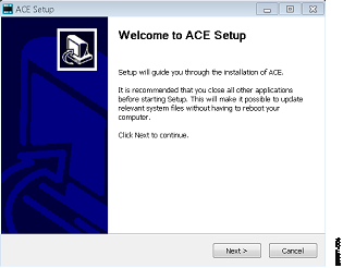
Click “Next >” to continue
Step 1.2: License Agreement
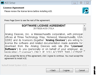
Read the software license agreement
Click “I Agree” to accept and continue
Step 1.3: Installation Location
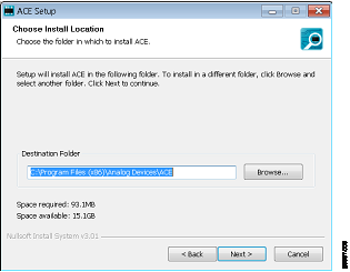
The default location is recommended
Click “Browse…” if you need to choose a different folder
Click “Next >” to continue
Step 1.4: Components Selection
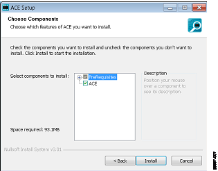
All ACE software components are pre-selected
Click “Install” to begin installation
Step 1.5: Windows Security Prompt
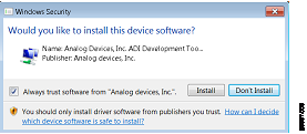
Click “Install” to install required drivers and components
Step 1.6: Installation in Progress
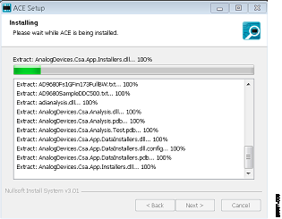
Wait for the installation to complete
No action required during this phase
This typically takes 1-3 minutes
Step 1.7: Installation Complete
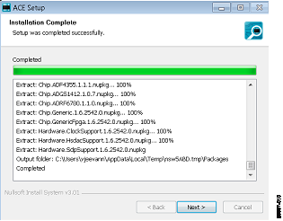
Click “Next >” when installation finishes
Click “Finish” to close the wizard
ACE software is now installed and ready to use
Step 2: Install SDP Controller Drivers
The SDP controllers (K1 and B1) use the same universal drivers.
Download SDPDrivers.exe from the link provided above
Double-click SDPDrivers.exe to begin driver installation
Follow the driver installation wizard:
Accept any UAC prompts
Click “Yes” or “Next” through all screens
Select “Automatically install drivers” if prompted
Restart your PC if prompted by the installation wizard
Driver installation is complete
Step 3: Install AD4170 Plugin
The AD4170 plugin extends ACE with device-specific features.
Option A: Direct Plugin Installation (Recommended)
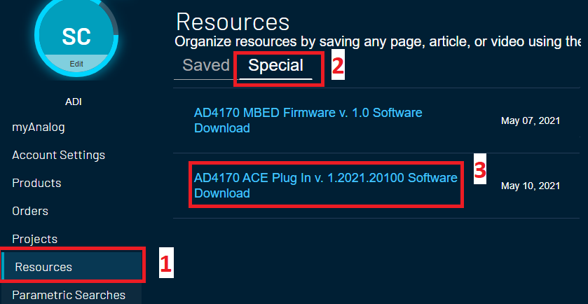
Login to your myAnalog.com account
Navigate to myAnalog.com
Access your Dashboard
Click on “Dashboard” or similar menu option
Locate the AD4170 Plugin
Look under “Special Resources” section
Find “AD4170 ACE Plug In V X.X Software Download”
(Note: Version number may differ)
Download the Plugin:
Step 3A.1: Plugin Download Page
A new tab/window opens with the download link
Step 3A.2: Accept License
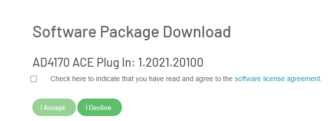
Read the software license agreement
Check the checkbox to accept terms
Click “I Accept”
Step 3A.3: Start Download
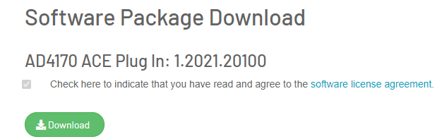
Click “Download”
File downloads to your Downloads folder (typically)
Install the Downloaded Plugin
Locate the downloaded file (usually named AD4170_PluginXXX.zip)
Double-click the file to start installation
Follow any installation prompts
Option B: Manual Plugin Installation (Alternative)
If direct installation doesn’t work, install via ACE Plugin Manager:
Open ACE Software
Click Start > All Programs > Analog Devices > ACE > ACE.exe
Navigate to Plugin Manager
Click the “Plug-in Manager” tab in the top-left panel
Configure Plugin Source
Click “Settings…” button
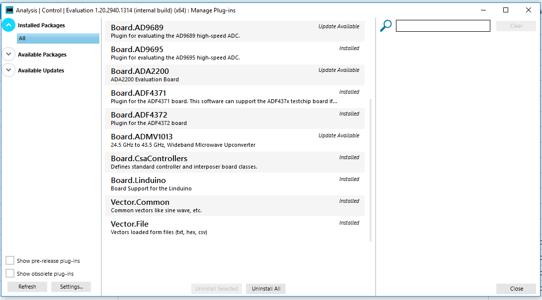
Click the “+” button next to “Zipped Plug-in Sources”
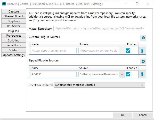
Add Plugin Path
In the “Name” field, enter:
AD4170Click the “…” button under “Source”
Browse to the location where you extracted the AD4170 plugin
Click “Ok”
Click “Close”
Plugin is now installed and will appear in ACE
Launching and Using ACE with SDP-K1
Initial Launch
Before launching ACE:
Ensure software installation is complete (all three components)
Ensure EVAL-AD4170-4ARDZ is connected to EVAL-SDP-CK1Z
Ensure all jumpers/links are in default positions
Do not connect USB yet if this is your first time
Launch ACE Software:
Start > All Programs > Analog Devices > ACE > ACE.exe
ACE main window opens showing Plug-in Manager tab
Now connect the USB-C cable to your PC (if not already connected)
Windows detects the SDP-K1 device and prompts for driver confirmation
Allow driver installation if prompted
Windows will recognize the device
Wait 5-10 seconds for device enumeration
The AD4170 Eval Board icon appears in “Attached Hardware” section
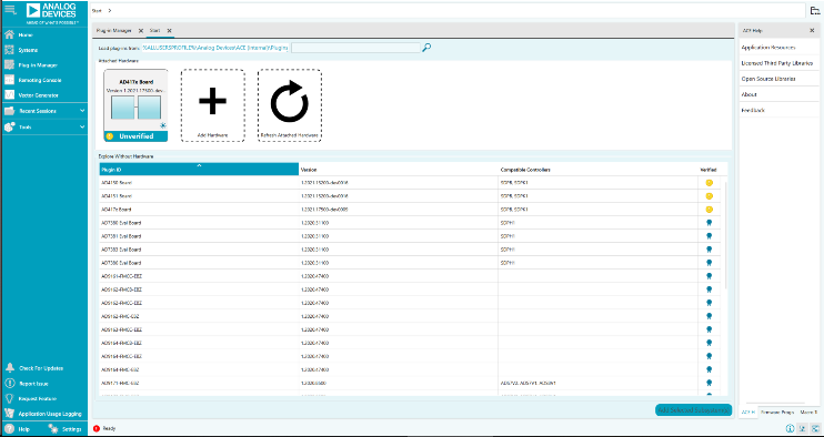
If the icon does not appear, see Troubleshooting section
Board View Window
The Board View shows the hardware structure and provides access to all functions:
Double-click the AD4170 Eval Board icon to open Board View
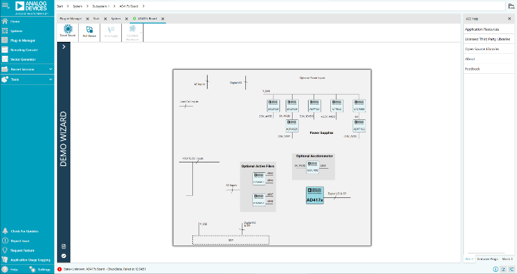
The Board View window opens showing the system architecture
Apply default configuration to verify communication:
Double-click the AD4170 chip icon
Click “Software Defaults” button
Click “Apply Changes”
Successful configuration indicates proper SDP-K1 communication
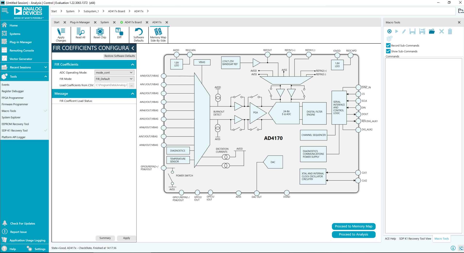
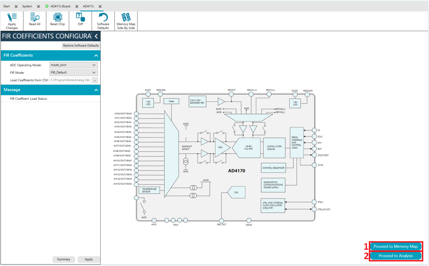
Configuration Interface
The Chip View window provides full access to AD4170 configuration:
Key Buttons and Functions:
Programmable Blocks (dark blue icons) - Click to configure functional blocks
Input channel configuration
Reference voltage selection
Data rate and filter settings
Output channel configuration
Proceed to Memory Map - Access low-level register configuration
Direct register read/write
Bitfield configuration
Save/load register settings
Proceed to Analysis - Access data capture and analysis
Real-time waveform display
Noise measurements
FFT analysis
Data export
Memory Map Tab
Access detailed AD4170 register configuration:
Click Memory Map button from Chip View
Register Tree displays on left side
Select any register to view/edit:
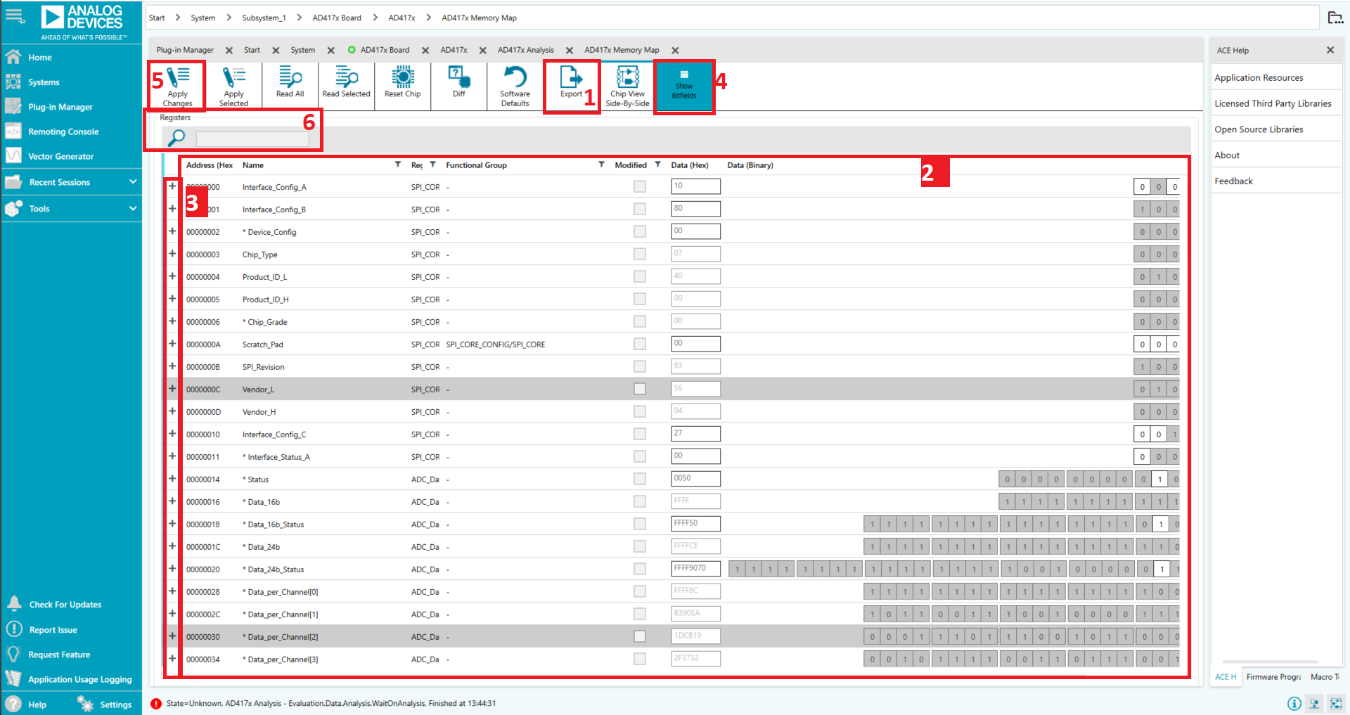
Register Value shows current value in hex
Individual Bits can be toggled or set directly
Bitfield Details show named fields and descriptions
Show Bitfield button expands field details
Save/Load Registers:
Save Button - Export all current register settings to file
Load Button - Import previously saved register configuration
Useful for storing different measurement configurations
Apply Changes - Write configuration to AD4170
Search Function - Find registers by name or address
Analysis Tab
The Analysis/Waveform tab displays real-time captured data:
Waveform Graph:
Shows each successive ADC sample
Mouse scroll wheel zooms in/out
Magnifying glass icon for zoom controls
Pan controls for scrolling through data
Capture Controls:
Samples field - Sets number of samples per batch
Run Once - Capture a single batch of samples
Run Continuously - Continuous data capture (click again to stop)
Data Display Options:
Codes Dropdown - Display as voltage or raw binary codes
Axis Controls - Auto-scale or fixed axis ranges
AC/DC Analysis - Select measurement type
Results Section:
Displays measured parameters for selected channel:
Peak-to-Peak Noise
RMS Noise
Effective Number of Bits (ENOB)
Signal Histogram
Signal Statistics (min, max, mean)
FFT Plot:
View frequency domain analysis:
Frequency spectrum display
Harmonic content identification
Signal-to-Noise Ratio (SNR)
Spurious-Free Dynamic Range (SFDR)
Total Harmonic Distortion (THD)
Export Data:
Click “Export” button in Results section
Choose save location in dialog
Data saved as Excel (.xlsx) file for further analysis
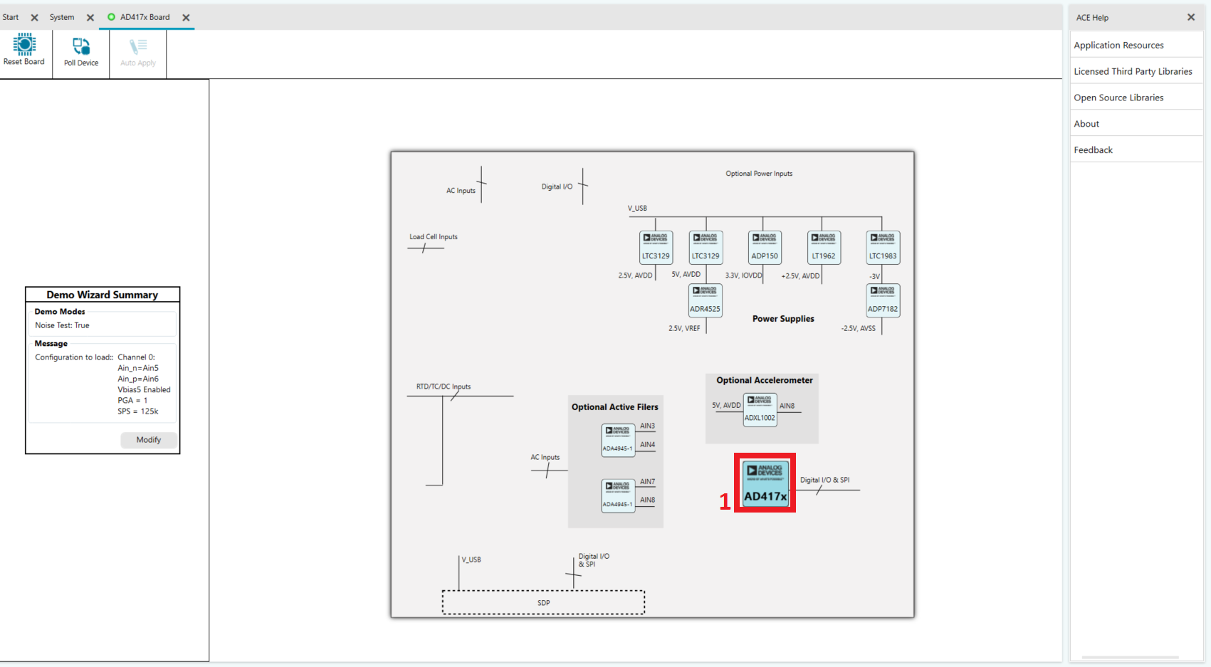
Demo Modes
Demo modes provide pre-configured setups for common measurement applications. Each demo automatically configures all necessary AD4170 settings.
Demo Mode Access
Open Chip View by double-clicking AD4170 in Board View
Locate Demo Wizard panel on left side of Chip View
May be collapsed/minimized
Click arrow to expand if needed
Available demos appear as selectable options
Available Demo Modes
Noise Test Demo - ADC noise floor characterization
2-Wire RTD Demo - Two-wire resistance temperature detector
3-Wire RTD Demo - Three-wire RTD with better accuracy
4-Wire RTD Demo - Four-wire RTD highest accuracy measurement
Thermocouple Demo - Thermocouple temperature sensor
Thermistor Demo - Thermistor temperature measurement
4-Wire Bridge Demo - Four-wire load cell/bridge measurement
6-Wire Bridge Demo - Six-wire bridge with separate excitation
Running Noise Test Demo (Example)
Step 1: Select Demo Mode
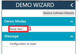
Click “Noise Test” in the Demo Wizard
Step 2: Review Settings
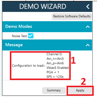
Pre-configured settings display
These are optimized for noise measurement
Click “Apply” to write to AD4170
Step 3: Configuration Complete
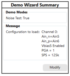
Demo confirms settings have been applied
Step 4: Open Chip View
Double-click AD4170 chip icon to open full Chip View
Step 5: Access Analysis Tools
Memory Map - Modify settings if needed
Analysis - Begin data capture
Step 6: Capture and Analyze Data
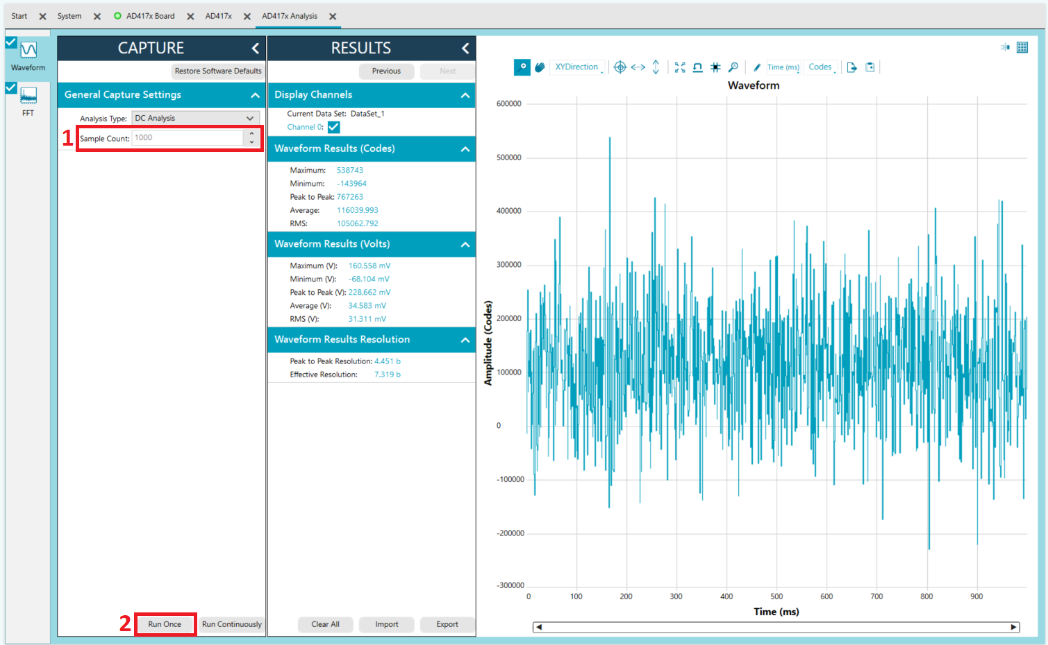
Set Sample Count to desired value (e.g., 1000 samples)
Click Run Once to capture samples
Results display in waveform graph and analysis section
Measure noise metrics:
Peak-to-Peak Noise (voltage)
RMS Noise (voltage)
Effective Resolution (bits)
Noise Density (nV/√Hz)
Other Demo Modes
Similar procedure for other demos:
Select the demo from Demo Wizard
Review and apply the pre-configured settings
Open Chip View to access Analysis tools
Capture data according to application requirements
Review results to verify proper configuration
Each demo is optimized for its specific measurement type and provides good starting points for custom configurations.
Virtual Evaluation Tool
ADI provides a Virtual Evaluation Tool for software-only exploration:
Access Virtual Evaluation:
Open your browser and navigate to:
OR
Visit the AD4170 product page at analog.com and find Virtual Eval link
Using Virtual Eval:
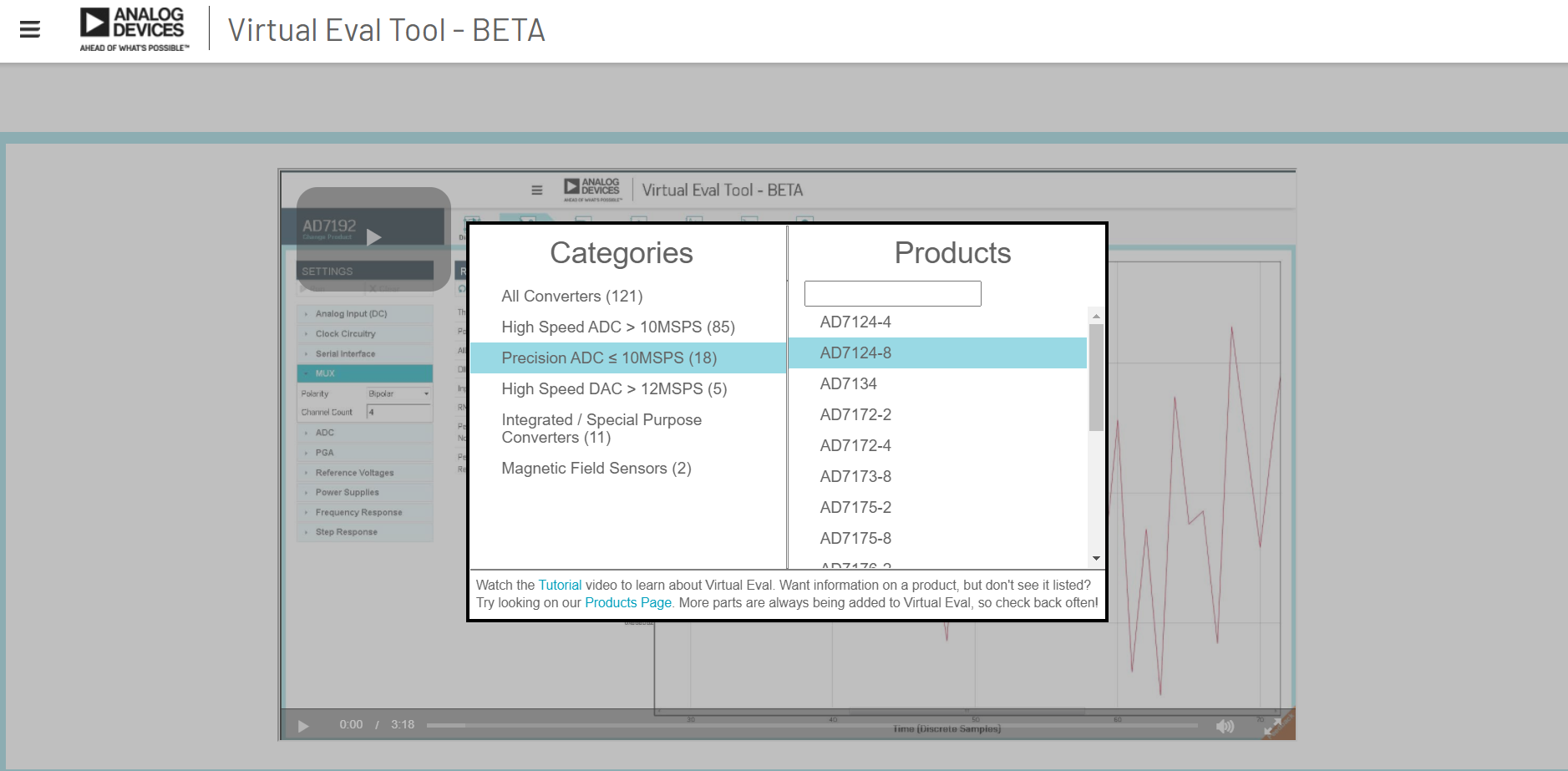
Navigate to “Precision ADC < 10MSPS” category
Find and select AD4170-4
Explore features and configurations
Simulate different measurement scenarios
Preview ACE software interface before hardware testing
Benefits:
No hardware required
Explore all features risk-free
Preview what physical evaluation will show
Plan measurements before running hardware tests
Reference Configuration
Default Reference Voltage (On-board ADR4525):
Default setting: 2.5V external reference
Set “Refin1(+/-)” field to 2.5V in Configuration tab
Adjust this value if using different reference source
Reference Options:
See the Hardware Guide for detailed reference voltage options:
Internal reference options
External reference inputs
Precision reference sources
Reference bypassing and stability
Data Capture Best Practices
Before Capturing Data:
Verify Reference Setting - Must match actual reference voltage
Check Input Range - Ensure signal is within configured range
Verify Connections - All sensor/signal connections secure
Allow Warm-up - Let system stabilize for 30-60 seconds after power-on
During Capture:
Set Appropriate Sample Count - 1000+ samples for noise analysis
Use Run Once First - Verify system is working before continuous capture
Monitor Results - Watch for unexpected patterns or errors
Save Configuration - Use Save button to preserve working setup
After Capture:
Review Results - Check noise, SNR, and other metrics
Export Data - Save to Excel for further analysis
Document Settings - Record successful configurations
Repeat Measurements - Verify reproducibility
Troubleshooting
Device Not Recognized
Symptom: AD4170 Eval Board icon doesn’t appear in Attached Hardware
Solutions:
Verify driver installation:
Check Windows Device Manager for unknown/error devices
Re-run SDPDrivers.exe if needed
Restart Windows if drivers were just installed
Check USB connection:
Verify USB-C cable is firmly connected
Try a different USB port (preferably USB 2.0 port)
Try a different USB cable (known good cable)
Avoid USB hubs - connect directly to PC
Verify evaluation board connection:
Ensure EVAL-AD4170-4ARDZ is properly seated on SDP-K1
Check that Arduino connectors are fully inserted
No loose or missing jumpers
Restart the system:
Disconnect USB cable
Close ACE software completely
Wait 10 seconds
Reconnect USB
Restart ACE
Check Windows Logs:
Device Manager > View > Show hidden devices
Look for unknown or error devices
Right-click > Update Driver
Communication Errors
Symptom: “Cannot communicate with device” or similar error message
Solutions:
Verify power and connections:
Check USB power is adequate
Verify all Arduino connector pins are aligned
Ensure evaluation board is fully seated
Check jumper settings:
Verify all hardware links are in default positions
Review Hardware Guide for correct configurations
Power cycle the system:
Disconnect USB cable
Wait 5 seconds
Reconnect USB and allow device detection
Apply default settings:
Click “Software Defaults”
Click “Apply Changes”
Wait for confirmation
Software Crashes
Symptom: ACE software crashes or freezes
Solutions:
Graceful shutdown:
Disconnect USB cable from SDP-K1
Close all ACE windows
Wait 5-10 seconds
Restart ACE
Reconnect USB after ACE opens
Clear cached data:
Close ACE completely
Delete ACE temporary files (if known location)
Restart ACE and reconnect device
Reinstall plugin:
If crashes persist, uninstall AD4170 plugin
Restart ACE
Reinstall AD4170 plugin fresh
Data Capture Issues
Symptom: No waveform appears or data looks incorrect
Solutions:
Verify reference voltage:
Check “Refin1(+/-)” setting matches actual reference
Default is 2.5V for on-board reference
Measure reference voltage if uncertain
Check input signal:
Verify signal is present at input connector
Check signal is within configured input range
Verify sensor/signal connections are secure
Run demo mode first:
Use Noise Test demo to verify basic operation
This confirms AD4170 is responding correctly
Then configure custom measurements
Check PGA setting:
Ensure gain is appropriate for signal level
Lower gain if signal is too large
Increase gain if signal is very small
Review data rate setting:
Some data rates may cause display issues
Try different data rate settings
Refer to datasheet for recommended rates
No Data Display
Symptom: Waveform graph shows no data even after “Run Once”
Solutions:
Apply default settings:
Click “Software Defaults”
Click “Apply Changes”
Verify with Noise Test demo first
Check sample count:
Ensure Samples field has reasonable value (e.g., 100)
Very large values may take time to acquire
Start with smaller samples (100-500) for testing
Verify channel is enabled:
Check that input channel is enabled in configuration
Verify in Memory Map that channel is active
Check data rate:
Some data rates may prevent data display
Try slower data rates first (e.g., 1 kSPS)
Refer to AD4170 datasheet for valid combinations
Recommended Next Steps
After successful evaluation with SDP-K1:
Save your configuration:
Use Memory Map > Save button
Store register configuration files for future use
Explore additional demo modes:
Test each demo relevant to your application
Compare noise performance across configurations
Create custom configurations:
Use Memory Map for register-level customization
Design for your specific sensor/measurement type
Consider Linux integration:
See Quick start guides for Linux driver guides
Plan transition to embedded system if needed
Review complete documentation:
Technical Support
For additional assistance:
EngineerZone Forums - Community support
AD4170-4 Product Page - Product information
Technical Datasheet - Device specifications