Production Testing
Note
This production test procedure applies to Rev E of the AD-APARD32690-SL board.
Overview
The purpose of the test procedure is to identify connectivity issues, poor soldering, and potential manufacturing defects. Some of the issues are directly identified by explicit part-targeted tests, others are implicit, by running adjacent tests.
Test Duration
Step Description |
Estimated Time (minutes) |
|---|---|
Test bench setup |
10 min |
Software test |
5 min |
Total time |
15 min |
Test Requirements
Required Hardware
1x AD-APARD32690-SL board as device under test (DUT)
1x AD-T1LUSB2.0-EBZ and USB cable
1x Raspberry Pi 4 + Power supply
1x MAX32625PICO (Daplink) programmer
1x Micro HDMI cable for Raspberry Pi
1x Mouse and keyboard for Raspberry Pi
1x SD test card
Required Software
The test image is provided on a pre-configured SD card that inserts into the Raspberry Pi SD card slot.
Required Setup
No. |
Steps |
|---|---|
1 |
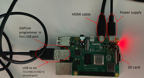
Insert the SD card into the Raspberry Pi and power it |
2 |
Connect the HDMI cable between RPi and the monitor, insert mouse and keyboard dongle into the RPi’s USB port |
3 |
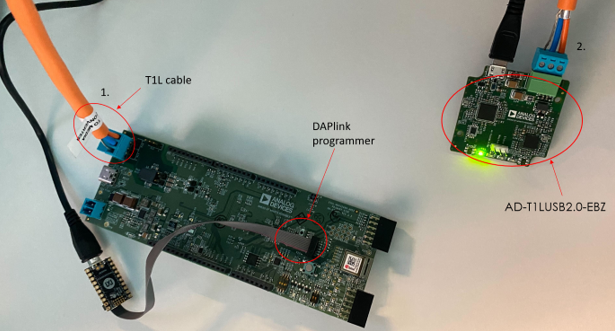
Connect MAX32625PICO Daplink programmer to RPi and DUT |
4 |
Connect the T1L cable to the AD-MAXARDUINO (DUT) board |
5 |
Connect the T1L cable to the AD-T1LUSB2.0-EBZ |
6 |
Connect the AD-T1LUSB2.0-EBZ to the RPi using a USB cable |
Test Process
Enabling Wi-Fi
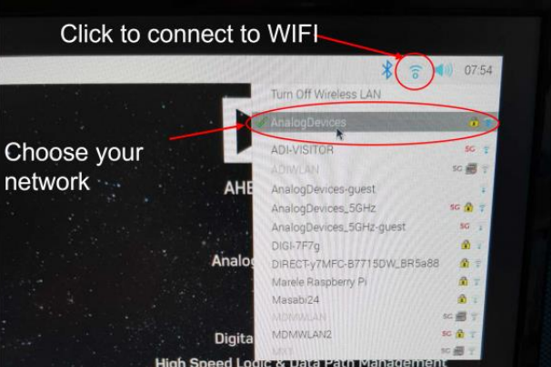
Before starting the testing procedure, make sure the Raspberry Pi is connected to Wi-Fi.
After the RPi boots the OS, press CONTROL+C to exit the test screen
Click on the Wi-Fi network you want to connect to
Type in the password
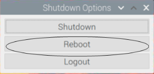
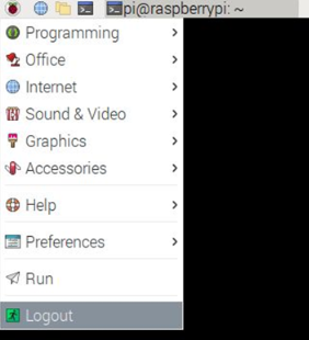
After successfully connecting, reboot the Raspberry Pi:
Running the Test Software
After the Raspberry Pi reboots, the test screen will appear on the monitor as shown below.
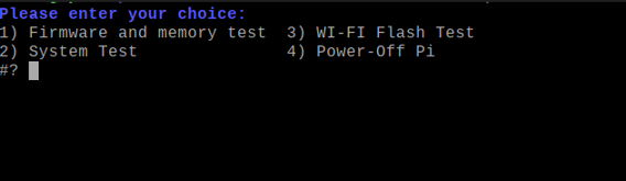
The following test menu should appear:
Please enter your choice:
1) Firmware and memory test
2) System Test
3) WI-FI Flash Test
4) Power-Off Pi
1) Firmware and Memory Test
Type “1” into the terminal then press ENTER to start 1) Firmware and memory test.
During this step, make sure the jumpers are in the correct position:
P38 and P56 jumpers are inserted
P50 and P55 are on position 2-3
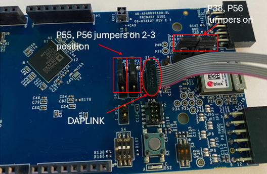
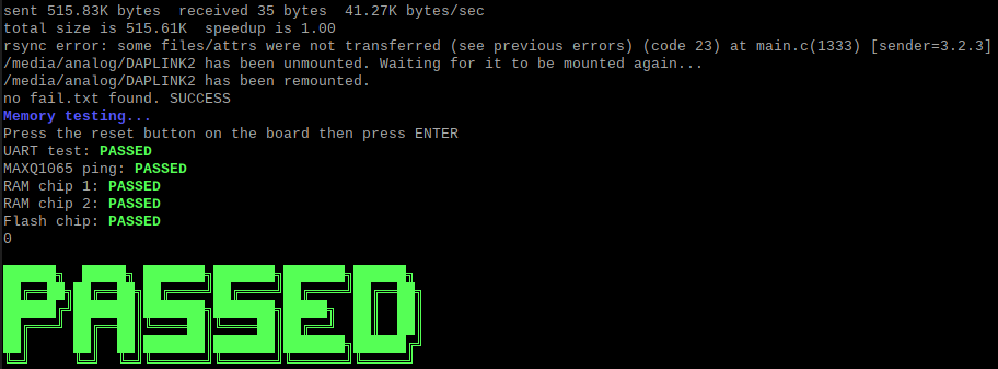
If the firmware is successfully written, you should see the message: “no fail.txt found. SUCCESS”
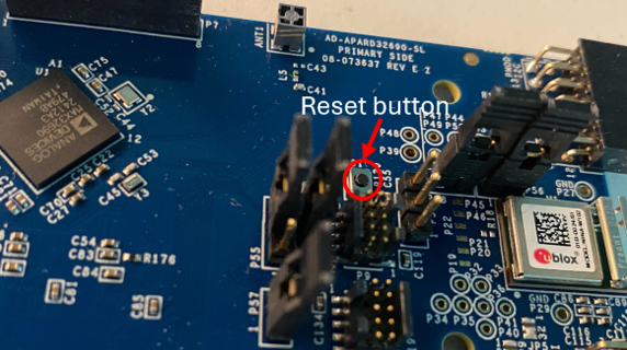
Press the reset button on the board when prompted:
Note
In case a failure occurred, a “FAILED” message will be displayed and you will be prompted to enter a new command.
If at any point a test fails, you can retry the test suite up to 3 times.
After the first test is passed, a green “PASSED” message will appear on the screen.
2) System Test
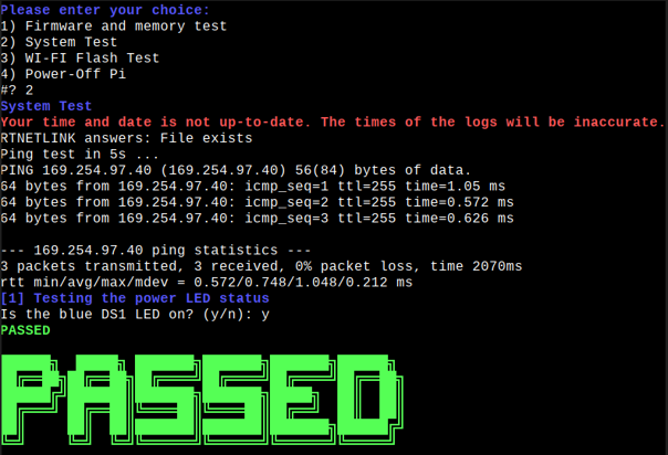
Type “2” into the terminal and press ENTER to start 2) System Test.
Note
In case a failure occurred, a “FAILED” message will be displayed.
After the test is passed, a green “PASSED” message will appear on the screen.
3) Wi-Fi Flash Test
Type “3” and press ENTER to start 3) Wi-Fi Flash Test.
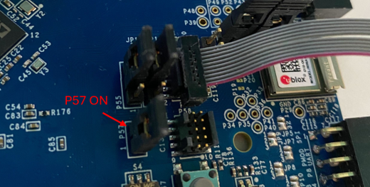
Make sure the jumpers are in the correct position:
P50 and P55 jumpers are on position 1-2
P38 and P56 jumpers are removed
P57 jumper is ON
Press ENTER to continue.
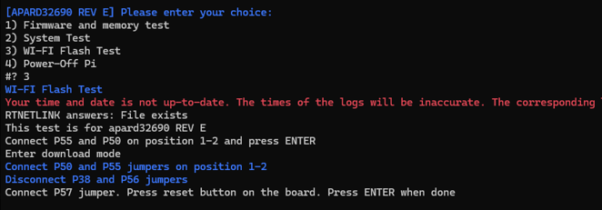
Press the reset button on the board and press ENTER to write the Wi-Fi chip firmware.
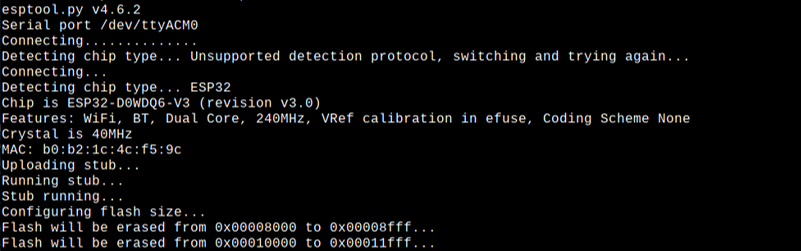
Disconnect the jumper previously connected to P57.
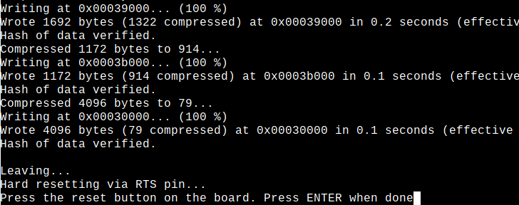
Press the RESET button on the board then press ENTER.
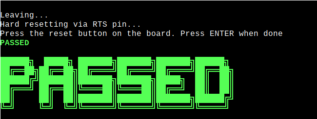
After successful completion:
Final Firmware Test
Go back to 1) Firmware and memory test and run it one more time. Make sure jumpers are in the correct position as stated earlier in this document:
P38 and P56 jumpers are inserted
P50 and P55 are on position 2-3
Note
If at any point a test fails, you should retry the test suite for up to 3 times.
Pass Criteria
After tests 1) Firmware and memory test, 2) System Test, 3) Wi-Fi Flash Test, and the final 1) Firmware and memory test have successfully passed, you can consider the DUT as being functional.
Place the jumpers in their final position:
P38, P56 installed
P55, P50 on position 2-3
4) Power-Off Pi
When you are done testing, press “4” and press ENTER to power-off the Raspberry Pi.