Hardware User Guide
Connectors and Jumper Configurations
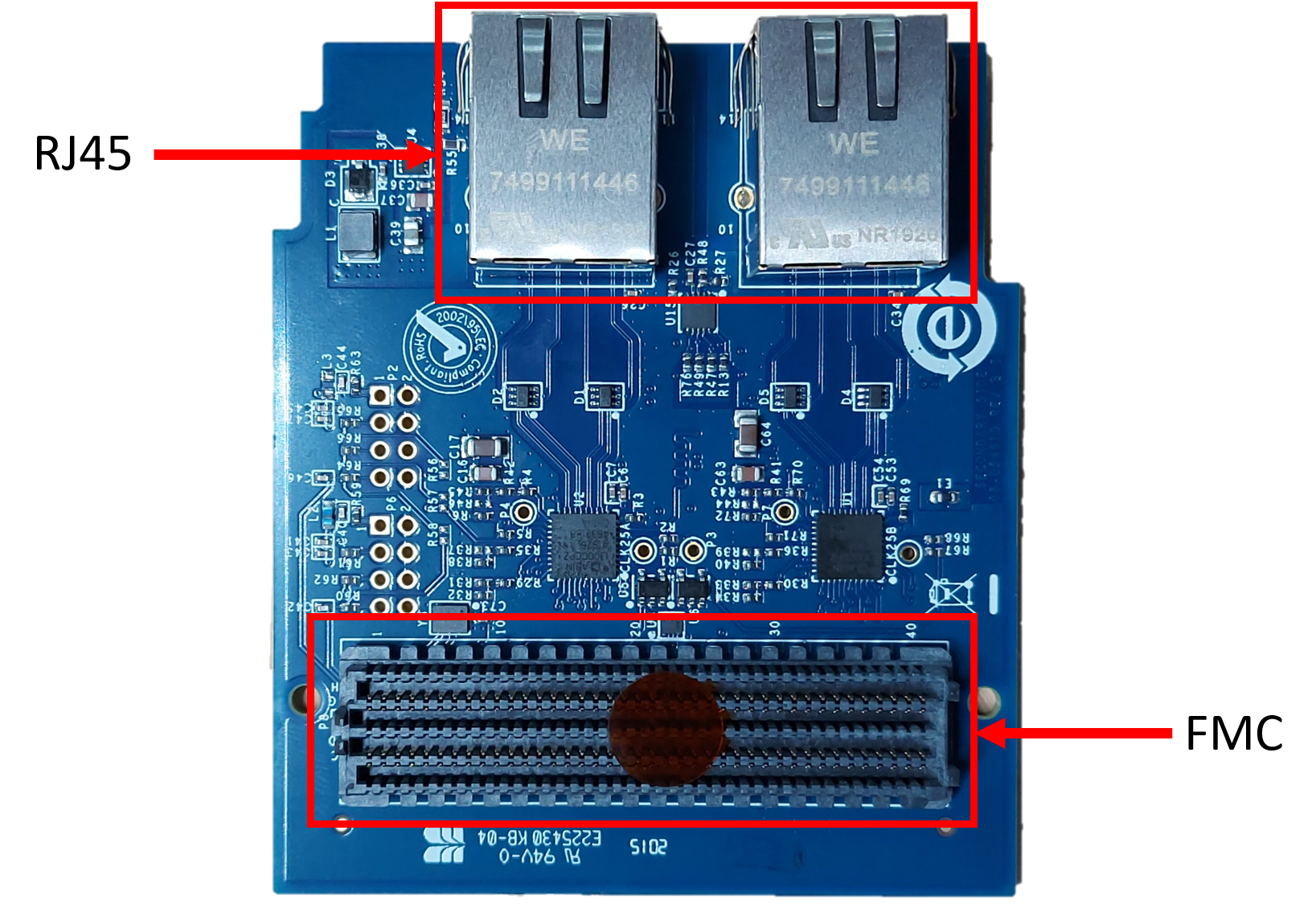
FMC Connector
The FMC connector connects to the LPC connector of the carrier board.
RJ45 Connectors
The RJ45 connectors M1 for Channel A and M2 for Channel B have built-in magnetics that help reduce the size of the board. Each is dedicated to a PHY interface (ADIN1300), allowing each channel to operate independently.
Configuration Resistors
MAC Interface
The pins for selecting the MAC interface are shared with the RX_CTL/RX_DV/CRS_DV pin and RXC/RX_CLK pin, which have weak internal pull-down resistors and are configured to RGMII mode with 2ns delay by default. The ADIN1300 MAC interface selection can be done via software but can also be hardware configured upon device power-up using the table below.
Configuration Modes
These configuration modes are used to set Auto-MDIX and PHY speed configurations for both PHY channels A and B.
PHY Interface
Both channels are configured upon power-up for:
10 Mbps Half/Full Duplex
100 Mbps Half/Full Duplex
1000 Mbps Full Duplex (Slave mode)
Auto-MDIX
LED Indicators
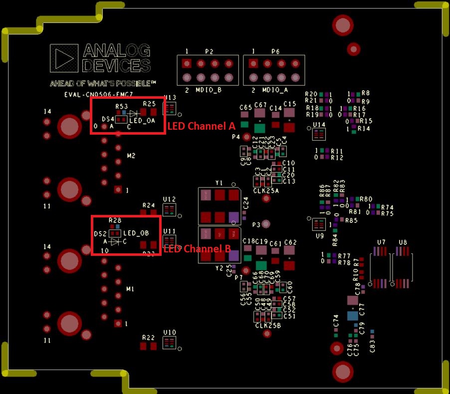
These LEDs indicate when a link is established and blink when there is activity.
PHY Channel A LED: DS4
PHY Channel B LED: DS2
Schematic, PCB Layout, Bill of Materials
Download
EVAL-CN0506-FMCZ Design & Integration Files
Schematics
Gerber Files
Bill of Materials
Allegro Layout Files
Assembly Files