ADMX2001B SPI Interface
The SPI interface can be used instead of the UART interface to send commands for configuration and measurement from the host. The SPI interface pins on the ADMX2001B module are SCK, SDI, SDO, and CS (B14-B17); see ADMX2001B Pin Configuration and Function Descriptions for the full pinout. On the evaluation board (EVAL-ADMX2001EBZ) the SPI interface is available on the Arduino style pin headers (P6 pins 5-8) and on both PMOD headers. See EVAL-ADMX2001EBZ Terminal Description for more details.
There is an example program for the SDP-K1 microcontroller that implements some functions to communicate with the ADMX2001B over the SPI interface. That code is available here: MBED SPI library.
SPI Protocol & Timing
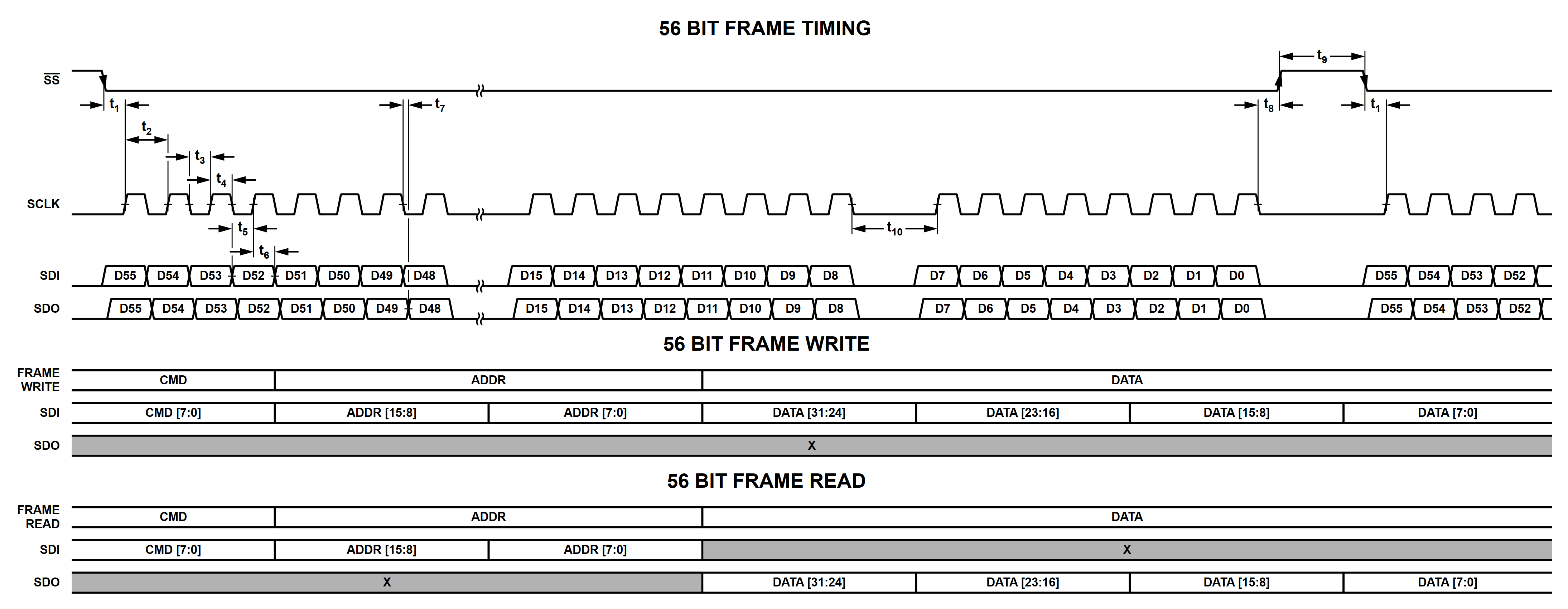
SPI Interface Timing:
Parameter |
Min |
Typical |
Max |
Unit |
Description |
Test Conditions / Comments |
|---|---|---|---|---|---|---|
SCLK Frequency |
20 |
MHz |
SPI clock frequency |
|||
T1 |
2.4 |
μsec |
SS falling edge to SCLK rising edge setup time |
|||
T2 |
45 |
nsec |
SCLK cycle time |
|||
T3 |
22.5 |
nsec |
SCLK low time |
|||
T4 |
22.5 |
nsec |
SCLK high time |
|||
T5 |
22.5 |
nsec |
Data setup time |
|||
T6 |
22.5 |
nsec |
Data hold time |
|||
T7 |
17.5 |
20 |
nsec |
SCLK falling edge to SDO valid |
||
T8 |
1.8 |
μsec |
SCLK falling edge to SS rising edge |
|||
T9 |
32 |
μsec |
Minimum SS high time |
With (MBED SPI library) |
||
T10 |
5.9 |
usec |
SCLK low time between bytes (byte-to-byte gap) |
SPI Command Summary
SPI Command Mapping:
SPI Command |
Name |
Function |
|---|---|---|
0x00 |
Status Read |
Return Host SPI Status |
0x01 |
Result Read |
Return the command result value in the DATAR word |
0x02 |
Clear Error |
Discard all previous SPI commands, results and errors, clear done bits including easurement done and command done, return SPI interface to the ready state |
0x03 |
Measurement Read |
Return the result of the measurement |
0x04 |
Calibrate |
Executes calibration routine |
0x05 |
Compensation |
Executes compensation routine |
0x06 |
Readcal |
Read the calibration coefficients for different gain combinations |
0x07 |
Reserved |
Reserved |
0x08 |
Storecal |
Write individual calibration coefficients |
0x09 |
Resetcal |
Reset calibration coefficients |
0x0C |
Rdcomp |
Read compensation coefficients |
0x0D |
Storecomp |
Write individual compensation coefficients |
0x0F |
Measure (z) |
Perform the requested measurement(s) and return the value(s) in the result FIFO |
0x10 |
Erase calibration |
Erase the calibration coefficients stored in the flash memory (1.2.0 only) |
0x11 |
Readsweep |
Read sweep points for the measured values |
0x12 |
Reset |
Reset the device |
0x13 |
Reserved |
Reserved |
0x14 |
Reserved |
Reserved |
0x15 |
Reserved |
Reserved |
0x16 |
Reserved |
Reserved |
0x17 |
Initiate |
Initiate the measurement |
0x18 |
Trigger |
Provide software trigger for measurement |
0x19 |
Reserved |
Reserved |
0x1A |
Abort |
Abort the measurement |
0x1B |
Calibration commit |
Commit the calibration coefficients to the flash |
0x1C |
Set password |
Update the password for committing calibration coefficients |
Configure Parameters:
SPI Command |
Name |
Function |
|---|---|---|
0x23 |
Frequency |
Set the DDS frequency to N Hz where N is an IEEE-754 single precision floating point value |
0x24 |
Reserved |
Reserved |
0x25 |
Magnitude |
Set the test signal magnitude to N volts, where N is an IEEE-754 single precision floating point |
0x26 |
Offset |
Set the test signal’s DC bias to N volts, where N is an IEEE-754 single precision floating point |
0x27 |
Reserved |
Reserved |
0x28 |
Voltage gain (CH0) |
Set the voltage gain (0 = 1, 1 = 2, 2 = 4, 3 = 8) |
0x29 |
Current gain (CH1) |
Set the current gain (0 = -96.154, 1 =- 961.54, 2 = -9615.4, 3 = -96154.0) |
0x2A |
Average |
Set the measurement loop to run N loops where N is an unsigned integer |
0x2B |
Mdelay |
Set the measurement delay between measurements selected by the ‘count’ command to N msec, where N is an IEEE-754 single precision floating point value |
0x2C |
Tdelay |
Set the trigger delay between measurement cycles selected by the ‘tcount’ command to N msec, where N is an IEEE-754 single precision floating point value |
0x2D |
Tcount |
Set the trigger count to N where N is an unsigned integer |
0x30 |
Sweep start |
Set the sweep start frequency/magnitude/offset |
0x31 |
Sweep end |
Set the sweep end frequency/magnitude/offset |
0x32 |
Sweep type |
Set the sweep type to off/frequency/magnitude/offset |
0x33 |
Sweep scale |
Set the sweep scale as linear/log |
0x34 |
Reserved |
Reserved |
0x38 |
Reserved |
Reserved |
0x39 |
Reserved |
Reserved |
0x3B |
Temperature unit |
Set the temperature unit as Celsius or Fahrenheit |
0x3C |
Reserved |
Reserved |
0x3D |
Reserved |
Reserved |
0x41 |
Display mode |
Set the measurement model output format |
0x42 |
Sample count |
Set the sample count for impedance/admittance measurements to N where N is an unsigned integer |
0x43 |
Correction mode |
Set calibration/compensation on or off |
0x44 |
Error check |
Set ADC/FPGA FIFO error checking on or off |
0x45 |
DC mode |
Enable or disable DC mode (must set offset instead of magnitude) |
0x46 |
Autorange |
Enable or disable autorange functionality |
0x47 |
Reserved |
Reserved |
0x48 |
Reserved |
Reserved |
0x49 |
Reserved |
Reserved |
0x4A |
Trigger mode |
Set trigger mode to internal or external trigger |
0x4F |
Reserved |
Reserved |
0x50 |
Reserved |
Reserved |
0x51 |
Self-test |
Run self-test |
0x52 |
Reserved |
Reserved |
0x53 |
Reserved |
Reserved |
0x56 |
GPIO control |
Set the digital output pins |
Read Parameters:
SPI Command |
Name |
Function |
|---|---|---|
0x8E |
Temperature |
Read the current module temperature, value returned is an IEEE-754 single precision floating point in degrees Celsius or Fahrenheit |
0x15 |
Version |
Read the module FW version: returns 32 bits, to be interpreted bytewise: [Major Version : Minor Version : Patch : Build Number] |
0xA3 |
Frequency |
Read the DDS frequency in Hz |
0xA4 |
Reserved |
Reserved |
0xA5 |
Magnitude |
Read the DDS magnitude |
0xA6 |
Offset |
Read the DC bias voltage |
0xA7 |
Reserved |
Reserved |
0xA8 |
Voltage gain |
Read the voltage gain setting |
0xA9 |
Current gain |
Read the current gain setting |
0xAA |
Average |
Read measurement average count |
0xAB |
Mdelay |
Read measurement delay |
0xAC |
Tdelay |
Read trigger delay |
0xAD |
Tcount |
Read the trigger count |
0xB0 |
Sweep start |
Read sweep start frequency/magnitude/offset |
0xB1 |
Sweep end |
Read sweep end frequency/magnitude/offset |
0xB2 |
Sweep scale |
Read sweep scale as linear/log |
0xB4 |
Reserved |
Reserved |
0xB8 |
Reserved |
Reserved |
0xB9 |
Reserved |
Reserved |
0xBB |
Temperature unit |
Read temperature unit (Celsius or Fahrenheit) |
0xBC |
Reserved |
Reserved |
0xBD |
Reserved |
Reserved |
0xC1 |
Display mode |
Read the measurement model output format |
0xC2 |
Sample count |
Read the sample count value |
0xC3 |
Reserved |
Reserved |
0xC4 |
Error check |
Read whether ADC/FPGA FIFO error checking is on or off |
0xC5 |
DC mode |
Read whether DC mode is on or off |
0xC6 |
Autorange |
Read whether autoranging is on or off |
0xC7 |
Reserved |
Reserved |
0xC8 |
Reserved |
Reserved |
0xC9 |
Reserved |
Reserved |
0xCA |
Trigger mode |
Read whether trigger mode is set to external or internal |
0xCD |
State |
Read whether the state is in Idle or Wait for Trigger |
0xCF |
Reserved |
Reserved |
0xD0 |
Reserved |
Reserved |
0xD1 |
Self-test |
Read self-test status |
0xD2 |
Unique ID |
Read the device unique ID |
0xD3 |
Warning |
Read warning status |
Output Format Options:
Data |
Format |
Description |
|---|---|---|
0 |
[Cs, Rs] |
Capacitance and equivalent series resistance |
1 |
[Cs ,D] |
Equivalent series capacitance and dissipation factor |
2 |
[Cs, Q] |
Equivalent series capacitance and quality factor |
3 |
[Ls, Rs] |
Inductance and equivalent series resistance |
4 |
[Ls ,D] |
Equivalent series inductance and dissipation factor |
5 |
[Ls, Q] |
Equivalent series inductance and quality factor |
6 |
[R, X] |
Impedance in rectangular coordinates (default) |
7 |
[Z, deg] |
Impedance in magnitude and phase in degrees |
8 |
[Z, rad] |
Impedance in magnitude and phase in radians |
9 |
[Cp, Rp] |
Capacitance and equivalent parallel resistance |
10 |
[Cp, D] |
Equivalent parallel capacitance and dissipation factor |
11 |
[Cp, Q] |
Equivalent parallel capacitance and quality factor |
12 |
[Lp, Rp] |
Inductance and equivalent parallel resistance |
13 |
[Lp, D] |
Equivalent parallel Inductance and dissipation factor |
14 |
[Lp, Q] |
Equivalent parallel inductance and quality factor |
15 |
[G, B] |
Admittance in rectangular coordinates |
16 |
[Y, deg] |
Admittance in magnitude and phase in degrees |
17 |
[Y, rad] |
Admittance in magnitude and phase in radians |
18 |
Reserved |
Warnings:
Code |
Warning |
|---|---|
0x00 |
No warning |
0x01 |
Reserved |
0x02 |
Initializing calibration coefficient failed |
0x04 |
Autorange disabled for sweep |
0x08 |
Autorange failed |
0x10 |
Sweep/measurement count is greater than supported |
0x20 |
Magnitude is greater than 1 volt for AC autorange. Setting it to 1 V for AC autorange. |
0x40 |
Offset is greater than 0 volts for AC autorange. Setting offset to 0 V for AC autorange. |
0x80 |
Offset is greater than 1 volt for DC autorange. Setting offset to 1 V for DC autorange. |
0x100 |
Offset is less than -1 volt for DC autorange. Setting offset to -1 V for DC autorange. |
Errors:
Code |
Error |
|---|---|
0x0000 |
Success. No error. |
0x0001 |
Command failure |
0x0002 |
Reserved |
0x0003 |
Invalid attribute |
0x0004 |
Attribute out of range |
0x0005 |
Invalid address for the command |
0x0006 |
Uncommitted calibration coefficients (can be treated as warning) |
0x0007 |
Invalid voltage/current gain |
0x0008 |
Invalid display type for DC resistance mode |
0x0009 |
Invalid sweep type for DC mode |
0x000A |
Invalid sweep range |
0x000B |
Invalid AC calibration coefficient type |
0x000C |
Reserved |
0x000D |
Invalid calibration type |
0x000E |
Invalid DC calibration coefficient type |
0x000F |
Calibration or compensation failed |
0x0010 |
Invalid command for Wait for Trigger state |
0x0020 |
Sweep start/end value can’t be zero for log scale |
0x0040 |
Sweep start/end should have same sign for log scale |
0x0080 |
Voltage ADC saturated |
0x0100 |
Current ADC saturated |
0x0200 |
Reserved |
SPI Command Details
Single Parameter Write
Procedure for writing single parameter command:
Do Frame Write with the respective command, address and data
Poll the status register until the Done bit is set
Once the Done bit is set, the command has been processed. If any warnings or error occur, respective bit will be set
Single Parameter Read
Procedure for reading single parameter command:
Do Frame Read with respective command, address and data
Poll the status register until the Done bit is set
Read result register if there is no error
Status Register Read (0x00)
The Status Register is a 32-bit read-only register and can be read using command 0x00. Register fields are shown in Status Register Field Descriptions.
Status Register:
Bit |
31 |
30 |
29 |
28 |
27 |
26 |
25:16 |
15:0 |
|---|---|---|---|---|---|---|---|---|
Field |
Measurement Done |
Command Done |
Error |
Warning |
FIFO Error |
Reserved |
Result FIFO Depth [9:0] |
Result/Error Code |
When any command is provided other than the Status, Result, and Measurement Read command, the Command Done bit will be cleared. After processing a given command, the Command Done bit will be set. The user must wait for this bit before providing the next command and/or to read data from The Result Register (0x01) or Measurement FIFO Register (0x03).
Status Register Field Descriptions:
Field |
Description |
|---|---|
Measurement Done |
Will be set after measurement is complete |
Command Done |
Will be set after processing a command |
Error |
Will be set if there are any errors while processing the command |
Warning |
Will be set if one or more warnings occur during the command process. Should use the read warning command to fetch the warning code |
FIFO Error |
Will be set when overflow or underflow occurs. This error will be cleared only by using the Clear Error command |
Result FIFO Depth [9:0] |
Contains a count of 32-bit data streams that are present in the FIFO |
Result/Error Code |
Contains the Error Code when the Error bit is set |
Do a Single Parameter Read with the command 0x00 to get the status.
Result Register Read (0x01)
Result register contains the processed output for few commands. Refer to the respective command’s section to know the data format and number of valid bits in the 32-bit field. Do a Single Parameter Read with 0x01 command to get the result.
Clear Error (0x02)
In order to clear SPI Measurement FIFO error, send the clear error command. It can also clear previous commands, measurement and command done bits, as well as retuls. It will return SPI interface to the ready state. Do a Single Parameter Write with 0x02 command and address & data field as zero to clear the error.
Measurement FIFO Read (0x03)
The Measurement FIFO contains either the measured value or sweep points. Refer to the respective command section to know the number of data and result data types stored in the FIFO. The Measurement FIFO should be read only when the Result FIFO Depth field in the status register is greater than 0. If the FIFO is read when it does not contain any data, FIFO Error will occur. Do a Single Parameter Read with 0x03 command to get the result.
Measure “Z” (0x0F)
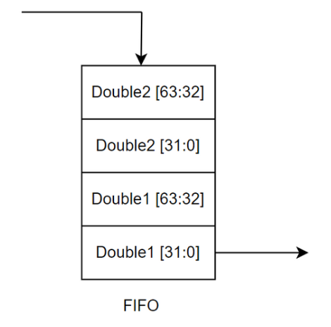
Initiates the measurement immediately and stores the result in the Measurement FIFO. Result will be in two IEEE-754 Double precision format. Since only 32-bit data format is supported during a Single Parameter Read, 64 bit double data is split as two 32 bit data and written into the FIFO. Commands that will affect the measurement are: output format, trigger count, sample count, offset, frequency, magnitude, voltage/current gain, sweep, measure delay, trigger delay.
Note: Trigger mode command will be ignored by this command.
The figure below shows how results are stored into the FIFO. The number of 32-bit data stored into the FIFO for each measurement can be calculated using the following equation,
No. of data = (sample count * trigger count) * 4
Procedure:
Configure the parameters (frequency, magnitude, etc…) with respective commands.
Do Frame Write with z (0x0F) command.
Poll status register until DONE and MEASURE DONE bit are set.
Read the result from FIFO using MEASUREMENT FIFO READ command.
Read sweep points using RDSWEEP command.
RDSWEEP (0x11)
After doing the measurement using z or trigger command, the sweep points
can be read using this command. This command returns the count or frequency or
magnitude or offset points as per the sweep type and count settings. Sweep
points are in double precision format and are stored as two 32-bit data into the
FIFO. These data can be read using the Measurement FIFO Read command. Number of
points = (sample count * trigger count) Procedure:
Do Frame Write with (0x11) in command and number of points in data field.
Poll register until Done bit is set.
Read the result from FIFO using the MEASUREMENT FIFO READ command.
Reset (0x12)
This command resets the entire device and sets the configuration parameters to its default value. Do a Single Parameter Write with reset command.
Initiate (0x17)
Initiate command initializes device for measurement and waits for the external/software trigger. Once external trigger is received, the measurement will be done automatically if external trigger is enabled and result will be populated into the FIFO. In “wait for trigger” state trigger, parameter read command, abort and reset commands are supported; other commands are not supported. Do a Single Parameter Write with the initiate command.
Trigger (0x18)
This command is treated as a software trigger for measuring the device under test. After measurement is completed, result will be stored into the FIFO. There are a few rules for using this command.
Should be provided only after providing initiate command i.e. when the device is in “wait for trigger” state.
Should be provided when software trigger is required. Should not be sent when external trigger is enabled.
Device will accept trigger command for trigger count times. For example, if trigger count is 2 only two triggers will be accepted.
External Trigger Procedure
Configure the device parameters. Enable external trigger with trigger mode command.
Send initiate command.
Provide external trigger and poll status register until Measurement Done bit is set.
Read the result from FIFO. Refer to Measure Command to know how the data is stored in the FIFO. If required, read sweep points as well.
Repeat steps 3 and 4 for tcount times.
Software Trigger Procedure
Configure the device parameters. Enable/Disable external trigger with trigger mode command.
Send initiate command.
Send trigger command and poll status register until Measurement Done bit is set.
Read the result from FIFO. Refer to Measure command to know how the data is stored in the FIFO. If required, read sweep points as well.
Repeat steps 3 and 4 for tcount times.
Abort (0x1A)
The abort command resets the state machine and sets it to “idle” state. It doesn’t change the configuration parameters. Do a Single Parameter Write with the abort command.
Frequency (0x23, 0xA3)
Frequency at which measurement should happen. To configure or fetch data, do a Single Parameter Write or Single Parameter Read.
Frequency Command Format:
Description |
Value |
|---|---|
Default |
1000 (unit:Hz) |
Write command |
0x23 |
Read command |
0xA3 |
Address |
0x0 |
Data range |
0 Hz, 0.2 Hz to 10000000 Hz |
Data type |
IEEE-754 Single precision floating point |
Magnitude (0x25, 0xA5)
Magnitude at which measurement should happen. To configure or fetch data, do a Single Parameter Write or Single Parameter Read.
Magnitude Command Format:
Description |
Value |
|---|---|
Default |
1 V |
Write command |
0x25 |
Read command |
0xA5 |
Address |
0x0 |
Data range |
0.13 to 2.25 V |
Data type |
IEEE-754 Single precision floating point |
Offset (0x26, 0xA6)
Offset voltage at which measurement should happen. To configure or fetch data, do a Single Parameter Write or Single Parameter Read.
Offset Command Format:
Description |
Value |
|---|---|
Default |
0 V |
Write command |
0x26 |
Read command |
0xA6 |
Address |
0x0 |
Data range |
-2.5 V to 2.5 V |
Data type |
IEEE-754 Single precision floating point |
Voltage Gain (0x28, 0xA8)
Set or get the voltage gain factor (0 = 1, 1 = 2, 2 = 4, 3 = 8). To configure or fetch data, do a Single Parameter Write or Single Parameter Read.
Note: This value will be ignored when auto range is enabled.
Voltage Gain Command Format:
Description |
Value |
|---|---|
Default |
0 |
Write command |
0x28 |
Read command |
0xA8 |
Address |
0x0 |
Data range |
0 to 3 |
Data type |
32-bit integer |
Current Gain (0x29, 0xA9)
Set or get the current gain factor (0 = 96.154, 1 = 961.54, 2 = 9615.4, 3 = 96154.0). To configure or fetch data, do a Single Parameter Write or Single Parameter Read.
Note: This value will be ignored when auto range is enabled.
Current Gain Command Format:
Description |
Value |
|---|---|
Default |
1 |
Write command |
0x29 |
Read command |
0xA9 |
Address |
0x0 |
Data range |
0 to 3 |
Data type |
32-bit integer |
Average (0x2A, 0xAA)
Number of samples to average while taking measurement. To configure or fetch data, do a Single Parameter Write or Single Parameter Read.
Average Command Format:
Description |
Value |
|---|---|
Default |
1 |
Write command |
0x2A |
Read command |
0xAA |
Address |
0x0 |
Data range |
1 to 65536 |
Data type |
32-bit integer |
Measure Delay MDELAY (0x2B, 0xAB)
Delay (time to wait) before doing each measurement. To configure or fetch data, do a Single Parameter Write or Single Parameter Read.
Measure Delay Command Format:
Description |
Value |
|---|---|
Default |
1 ms |
Write command |
0x2B |
Read command |
0xAB |
Address |
0x0 |
Data range |
0.0 to 65536.0 |
Data type |
IEEE-754 Single precision floating point |
Trigger Delay TDELAY (0x2C, 0xAC)
Delay (time to wait) after receiving each (internal/external) trigger. This delay is necessary for the AC output signal to get settle before doing the measurement. To configure or fetch data, do a Single Parameter Write or Single Parameter Read.
Trigger Delay Command Format:
Description |
Value |
|---|---|
Default |
4 ms |
Write command |
0x2C |
Read command |
0xAC |
Address |
0x0 |
Data range |
0.0 to 65536.0 |
Data type |
IEEE-754 Single precision floating point |
Trigger Count TCOUNT (0x2D, 0xAD)
Number of time to trigger the sweep measurement. To configure or fetch data, do a Single Parameter Write or Single Parameter Read.
Note: Only 256 measurement results can be stored in the measurement FIFO. If sample count * trigger count is greater than 256, readings will be lost.
Trigger Count Command Format:
Description |
Value |
|---|---|
Default |
1 |
Write command |
0x2D |
Read command |
0xAD |
Address |
0x0 |
Data range |
1 to 65536 |
Data type |
32-bit integer |
Sweep Start (0x30, 0xB0)
Set or get the sweep start frequency or magnitude or offset. To configure or fetch data, do a Single Parameter Write or Single Parameter Read.
Sweep Start Command Format:
Description |
Value |
|---|---|
Default |
0 |
Write command |
0x30 |
Read command |
0xB0 |
Address |
0x0 |
Data range |
Frequency: 0.2 to 10000000 (unit: Hz) Magnitude: 0.13 to 2.25 (unit: V) Offset: -2.5 to +2.5 (unit: V) |
Data type |
IEEE-754 Single precision floating point |
Sweep End (0x31, 0xB1)
Set or get the sweep end frequency or magnitude or offset. To configure or fetch data, do a Single Parameter Write or Single Parameter Read.
Sweep End Command Format:
Description |
Value |
|---|---|
Default |
1 |
Write command |
0x31 |
Read command |
0xB1 |
Address |
0x0 |
Data range |
Frequency: 0.2 to 10000000 (unit: Hz) Magnitude: 0.13 to 2.25 (unit: V) Offset: -2.5 to +2.5 (unit: V) |
Data type |
IEEE-754 Single precision floating point |
Sweep Type (0x32, 0xB2)
Set or get the sweep type (0 = off, 1 = frequency, 2 = offset, 3 = magnitude). To configure or fetch data, do a Single Parameter Write or Single Parameter Read.
Sweep Type Command Format:
Description |
Value |
|---|---|
Default |
0 |
Write command |
0x32 |
Read command |
0xB2 |
Address |
0x0 |
Data range |
0 to 3 |
Data type |
32-bit integer |
Sweep Scale (0x33, 0xB3)
Set or get the sweep scale (0 = linear, 1 = logarithmic). To configure or fetch data, do a Single Parameter Write or Single Parameter Read.
Sweep Scale Command Format:
Description |
Value |
|---|---|
Default |
0 |
Write command |
0x33 |
Read command |
0xB3 |
Address |
0x0 |
Data range |
0 or 1 |
Data type |
32-bit integer |
Temperature Unit (0x3B, 0xBB)
Set or get the temperature unit (0 = Fahrenheit, 1 = Celsius). To configure or fetch data, do a Single Parameter Write or Single Parameter Read.
Temperature Unit Command Format:
Description |
Value |
|---|---|
Default |
1 |
Write command |
0x3B |
Read command |
0xBB |
Address |
0x0 |
Data range |
0 or 1 |
Data type |
Boolean |
Output Format (0x41, 0xC1)
Set or get the output format, formats listed in the table below. To configure or fetch data, do a Single Parameter Write or Single Parameter Read.
Output Format Command Format:
Description |
Value |
|---|---|
Default |
6 |
Write command |
0x41 |
Read command |
0xC1 |
Address |
0x0 |
Data range |
0 to 17 |
Data type |
32-bit integer |
Sample Count (0x42, 0xC2)
Set or get the number of readings to be taken in a sweep. To configure or fetch data, do a Single Parameter Write or Single Parameter Read.
Note: Only 256 measurement results can be stored in the measurement FIFO. If sample count * trigger count is greater than 256, readings will be lost.
Sample Count Command Format:
Description |
Value |
|---|---|
Default |
1 |
Write command |
0x42 |
Read command |
0xC2 |
Address |
0x0 |
Data range |
1 to 32768 |
Data type |
32-bit integer |
Correction Mode (0x43, 0xC3)
Set or get the correction mode (0 = off, 1 = calibration, 2 = calibration + compensation). To configure or fetch data, do a Single Parameter Write or Single Parameter Read.
Note: Compensation cannot be used without calibration being enabled. Calibration must be turned on before compensation can be turned on.
Correction Mode Command Format:
Description |
Value |
|---|---|
Default |
1 |
Write command |
0x43 |
Read command |
0xC3 |
Address |
0x0 |
Data range |
0 to 2 |
Data type |
32-bit integer |
Error Check (0xC4, 0x0)
Set or get ADC saturation error checking (0 = disable, 1 = enable). To configure or fetch data, do a Single Parameter Write or Single Parameter Read.
Error Check Command Format:
Description |
Value |
|---|---|
Default |
0x44 |
Write command |
0xC4 |
Read command |
0x0 |
Address |
0x0 |
Data range |
0 or 1 |
Data type |
Boolean |
DC Mode (0x45, 0xC5)
Set or get DC mode (1 = disable, 0 = enable). To configure or fetch data, do a Single Parameter Write or Single Parameter Read.
Note: In order to do DC measurement, DC mode should be enabled (set parameter to 0) and frequency should be set to 0 Hz. Since the AC source is off in DC mode, the DC offset should be set to the desired value.
DC Mode Command Format:
Description |
Value |
|---|---|
Default |
1 (disabled) |
Write command |
0x45 |
Read command |
0xC5 |
Address |
0x0 |
Data range |
0 or 1 |
Data type |
Boolean |
Auto Range (0x46, 0xC6)
Set or get Auto ranging of voltage and current gain (0 = disable, 1 = enable). To configure or fetch data, do a Single Parameter Write or Single Parameter Read.
Note1: When auto range is enabled, voltage gain & current gain settings will be updated automatically.
Note2: Auto range will be disabled during calibration, compensation and when sweep type is “frequency or offset or magnitude”
Auto Range Command Format:
Description |
Value |
|---|---|
Default |
1 |
Write command |
0x46 |
Read command |
0xC6 |
Address |
0x0 |
Data range |
0 or 1 |
Data type |
Boolean |
Trigger Mode (0x4A, 0xCA)
Set or get Trigger mode (0 = internal/software, 1 = external). To configure or fetch data, do a Single Parameter Write or Single Parameter Read. Note: This mode will be ignored during calibration, compensation and measure (Z) command.
Trigger Mode Command Format:
Description |
Value |
|---|---|
Default |
0 |
Write command |
0x4A |
Read command |
0xCA |
Address |
0x0 |
Data range |
0 or 1 |
Data type |
Boolean |
State (0xCD)
This command reads the current state of the device. Value 0 means device is in
idle state and 1 means device is in wait for trigger state. Do a
Single Parameter Read to fetch the state.
State Machine Register Format:
Description |
Value |
|---|---|
Default |
0 |
Read command |
0xCD |
Address |
0x0 |
Data range |
0 or 1 |
Data type |
32-bit integer |
Self-Test (0x51, 0xD1)
Self-test runs after powering on the device. Self-test (0x51) command initiates the self-test routine and returns pass or fail in the error code field in the status register. Self-test (0xD1) reads the self-test status code in result register. To initiate self-test, do Single Parameter Write and to fetch status code, do a Single Parameter Read.
Note: Before initiating self-test make sure test leads/test fixture is in the open configuration, otherwise the analog test will fail. The self-test does not need to pass on every boot for the board to function properly.
Self-Test Command Format:
Description |
Value |
|---|---|
Default |
0 |
Run command |
0x51 |
Read command |
0xD1 |
Address |
0x0 |
Data range |
0 to 63 |
Data type |
32-bit integer |
Bit |
Value |
|---|---|
0 |
ADC IC test failed |
1 |
DAC IC test failed |
2 |
Temperature IC test failed |
3 |
Analog test failed |
4 |
Unique ID test failed |
5 |
EEPROM/Flash IC test failed |
Unique ID (0xD2)
Unique device ID can be fetched can be using this command. Do a Single Parameter Read with the respective command and address. The unique ID is a 64-bit integer, but frame format is only 32-bit data, so it is split into multiple address.
Unique ID Register Format:
Description |
Value |
|---|---|
Default |
|
Read command |
0xD2 |
Address |
0x0: lower 32-bit, 0x1: higher 32-bit |
Data range |
0 to 4294967295 |
Data type |
32-bit integer |
Warning Status (0xD3)
Warning status can be fetched using this command. Do a Single Parameter Read with this command. Refer to the list of warnings to know the description of the code.
Warning Status Register Format:
Description |
Value |
|---|---|
Default |
0 |
Read command |
0xD3 |
Address |
0x0 |
Data range |
0 to 65536 |
Data type |
32-bit integer |
Calibration Command Summary
The section below describes all calibration commands and utilities.
CAL (0x04) / COMP (0x05)
CAL/COMP command is used to perform open, short and load calibration/compensation. The Rt and Xt values for load calibration/compensation are sent in the data field as a 32-bit floating point. For running open/short/load calibration or open/short/load compensation commands the data field is redundant. The result register will contain the appropriate error code if the calibration or compensation fails. Open and short calibration/compensation must be performed before load calibration/compensation to proceed. Refer to the Calibration and Compensation Commands table for details about the address and data fields.
Open/Short/Load Calibration Command Mapping
Command |
Address |
Data range |
Data type |
Description |
|---|---|---|---|---|
0x04 |
0 |
N/A |
32-bit integer |
Reserved |
1 |
N/A |
32-bit integer |
Run short circuit calibration |
|
2 |
N/A |
32-bit integer |
Run open circuit calibration |
|
3 |
N/A |
32-bit integer |
Run load calibration with configured Rt/Xt. Must have Rt/Xt configured before running load calibration. |
|
4 |
Rt as an IEEE-754 floating point |
32-bit integer |
Set Rt for load calibration |
|
5 |
Xt as an IEEE-754 floating point |
32-bit integer |
Set Xt for load calibration |
|
0xFF |
N/A |
32-bit integer |
Run reload calibration. Will load the nearest frequency calibration coefficients from the nonvolatile memory and store them in the RAM |
Note the last row has an address field 0xFF. This command/address combination is for a new command called reload calibration (starting in firmware 1.2.2). To run this command, the address filed needs to be set as 0xFF. The reload command will load the nearest frequency calibration coefficients from the nonvolatile memory and store them in the RAM. This is especially useful when user wants to read calibration coefficients taken at different frequencies (i.e. calibration over frequency). Say a new frequency is set, user will need to run reload calibration first, then perform CAL_READ (0x06) to load calibration coefficients at that specific frequency from FLASH to RAM. Otherwise, calibration coefficients successfully read at previous set frequency will be misread for the new frequency.
Open/Short/Load Compensation Command Mapping
Command |
Address |
Data range |
Data type |
Description |
|---|---|---|---|---|
0x05 |
0 |
N/A |
32-bit integer |
Reserved |
1 |
N/A |
32-bit integer |
Run short circuit compensation |
|
2 |
N/A |
32-bit integer |
Run open circuit compensation |
|
3 |
N/A |
32-bit integer |
Run load compensation with configured Rt/Xt. Must have Rt/Xt configured before running load compensation. |
|
4 |
Rt as an IEEE-754 floating point |
32-bit integer |
Set Rt for load compensation |
|
5 |
Xt as an IEEE-754 floating point |
32-bit integer |
Set Xt for load compensation |
CAL_COMMIT (0x1B)
CAL_COMMIT command is used to commit the calibration data to the flash after performing a password check. The password is written to the input password buffer as ASCII values of characters corresponding to the first 12 address’s locations or fields (with values in decimal). The address field directs information from the data field to various locations or initiates specific processes. The address location 12 is reserved for the Unix timestamp of the commit. Sending 0xFF in the address field will compare the password stored and commit the calibration data if the password matches the set password. In case the password is incorrect sending 0xFF will clear the input password buffer. Performing calibration or using the CAL_STORE to store calibration coefficients is needed before committing the calibration data. Refer to the Commit Calibration Commands table for details about the address and data fields.
Commit Calibration Command Mapping
Write Command |
Address |
Data range |
Data type |
Description |
|---|---|---|---|---|
0x1B |
0 1 2 … 10 11 |
26 upper and 26 lower case letters, 10 digits, and 33 special characters Space char (0x20) not allowed |
ASCII value of Nth character of password, as indicated by address field value |
Send char 0 of the password Send char 1 of the password Send char 2 of the password … Send char 10 of the password Send char 11 of the password |
12 |
-2147483648 to 2147483647 |
32-bit integer |
Commit Timestamp, Unix epoch time in seconds since Jan 1, 1970 UTC |
|
0xFF |
N/A |
N/A |
Compare set password with the stored password, commit calibration data if the password is correct |
CAL_READ (0x06) / COMP_READ (0x0C)
The CAL_READ command is used to read the calibration coefficients and data by setting specific calibration address in the command’s address field. COMP_READ functions similarity, which reads the compensation coefficients and data by setting the corresponding compensation address in the command’s address field. The calibration and compensation data is polled from result register. The distinction between coefficients and data is that coefficients refer to the 12 AC coefficients (calibration and compensation) and 2 DC coefficients (calibration only), while data refers to status (open/short/load calibration or compensation), frequency and temperature. For more details refer to Read Calibration/Compensation Command Mapping Table. Such address is access bitwise as follows:
The bit 3 to bit 0 of the address need to be set to the voltage and current gain for which the calibrations/compensation coefficients are to be read.
The bit 8 to bit 4 of the address field are redundant.
The bit 9 of the address can be used to toggle between two modes, calibration/compensation data read mode and calibration/compensation coefficients read mode. In case calibration/compensation coefficients read mode is used, the bit 14 is used to either read the MSB or the LSB of the 64-bit double valued calibration/compensation coefficient. The calibration/compensation coefficient is set by appropriately setting the bit 13 to bit 10. In case calibration/compensation data read mode is used, ignores bit 14 and can be used to read the calibration/compensation data in its respective formats.
To send CAL_READ/COMP_READ commands, user can build a compound address using bitwise to the left operation to construct each sub-filed based on 2-bit voltage gain, 2-bit current gain, 1-bit mode type, 4-bit coefficient type, and (if relevant) 1-bit coefficients LSB/MSB. After writing the address and getting a successful status, the result register will contain the MSB/LSB of the calibration coefficient or the requested calibration data. The same applies to compensation read too. Refer to the Calibration Commands and Compensation Commands table for details about the address and data fields.
Read Calibration Command Mapping
Read Command |
Address |
Data range |
Data type |
Description |
|---|---|---|---|---|
0x06 |
Bit 14 |
0 or 1 |
1-bit address |
Coefficients LSB/MSB is decided by bit 14 (for calibration coefficient read, will be invalid for calibration data read). 0 - LSB of double value 1 - MSB of double value |
Bit 13 to bit 10 |
For calibration coefficients refer to Table “Calibration/ Compensation Coefficients and Data Register Format”. For calibration data: - 0000 for AC calibration status - 0001 for AC calibration frequency - 0010 for AC calibration temperature |
4-bit address |
Calibration coefficient or calibration data to be read |
|
Bit 9 |
0 or 1 |
1-bit address |
Flip between calibration coefficients/calibration data read mode 0 - Read calibration coefficients 1 - Read calibration data |
|
Bit 8 to bit 4 |
N/A |
N/A |
Redundant bits, can default to 0 |
|
Bit 3 to bit 2 |
0 to 3, i.e. 00, 01, 10, 11 |
2-bit address |
Current gain of coefficients |
|
Bit 1 to bit 0 |
0 to 3, i.e. 00, 01, 10, 11 |
2-bit address |
Voltage gain of coefficients |
Read Compensation Command Mapping
Read Command |
Address |
Data range |
Data type |
Description |
|---|---|---|---|---|
0x0C |
Bit 14 |
0 or 1 |
1-bit address |
Coefficients LSB/MSB is decided by bit 14. 0 - LSB of double value 1 - MSB of double value |
Bit 13 to bit 10 |
For calibration coefficients refer to Table “Calibration/ Compensation Coefficients and Data Register Format”. For compensation data: - 0000 for AC compensation status - 0001 for AC compensation frequency - 0010 for AC compensation temperature |
4-bit address |
Compensation coefficient or compensation data to be read |
|
Bit 9 |
0 or 1 |
1-bit address |
Flip between compensation coefficients/compensation data read mode 0 - Read compensation coefficients 1 - Read compensation data |
|
Bit 8 to bit 4 |
N/A |
N/A |
Redundant bits, can default to 0 |
|
Bit 3 to bit 2 |
0 to 3, i.e. 00, 01, 10, 11 |
2-bit address |
Current gain of coefficients |
|
Bit 1 to bit 0 |
0 to 3, i.e. 00, 01, 10, 11 |
2-bit address |
Voltage gain of coefficients |
When reading the coefficients, there may be instances where they don’t exist for the user-specified frequency and voltage/current gain settings. When implementing the command in SPI, users need to provide a set of default coefficients if the CAL_READ or COMP_READ command triggers an error flag (flag_ERROR). The default values commonly used by the ADMX2001 are as follows.
When reading calibration or compensation status (command 0x06 or 0x0C) by correctly accessing the address value 00001 for bit 13 to bit 9, following masks will return, each indicating a different type of calibration coefficients are received.
0x000F - indicates open calibration coefficients are received
0x00F0 – indicates short calibration coefficients are received
0x0F00 – indicates load calibration coefficients are received
Default Calibration/Compensation Coefficient Values
Calibration/Compensation Coefficients |
Default values |
|---|---|
Ro |
1.00E+06 |
Xo |
1.00E+06 |
Go |
0 |
Bo |
0 |
Rs |
0 |
Xs |
0 |
Gs |
1.00E+06 |
Bs |
1.00E+06 |
Rg |
-1.00E+06 |
Xg |
-1.00E+06 |
Gg |
-1.00E+06 |
Bg |
-1.00E+06 |
Rdg |
1.00E+00 |
Rdo |
0 |
Calibration/Compensation Coefficients and Data Register Format
Type |
Address (Bit 13 to Bit 9) |
Value returned in result register |
|---|---|---|
AC coefficients, applicable to both calibration and compensation |
0b00000 |
Ro |
0b00010 |
Xo |
|
0b00100 |
Go |
|
0b00110 |
Bo |
|
0b01000 |
Rs |
|
0b01010 |
Xs |
|
0b01100 |
Gs |
|
0b01110 |
Bs |
|
0b10000 |
Rg |
|
0b10010 |
Xg |
|
0b10100 |
Gg |
|
0b10110 |
Bg |
|
AC calibration/ compensation data |
0b00001 |
AC calibration status (32-bit integer) |
0b00011 |
AC calibration frequency (IEEE-754 Floating point) |
|
0b00101 |
AC calibration temperature (IEEE-754 Floating point) |
|
Below: only for CAL_READ, invalid addresses for COMP_READ |
||
DC calibration coefficients |
0b11000 |
Rdo |
0b11010 |
Rdg |
|
DC calibration data |
0b00111 |
DC calibration status (32 bit int) |
0b01001 |
DC calibration frequency (IEEE-754 Floating point) |
|
0b01011 |
DC calibration temperature (IEEE-754 Floating point) |
RESETCAL (0x09)
CAL_RESET command is used to reset the calibration coefficients. To clear calibration coefficients for a particular voltage and current gain setting, specify the first 4 address bits to the gain values. To clear all calibration coefficients, the address can be set to 0xFF. For running calibration reset commands the data field is redundant. Refer to the Reset Calibration Commands table for details about the address and data fields.
Reset Calibration Command Mapping
Write Command |
Address |
Data range |
Data type |
Description |
|---|---|---|---|---|
0x09 |
Bit 1 to bit 0 |
N/A |
N/A |
Voltage gain of coefficients |
Bit 3 to bit 2 |
N/A |
N/A |
Current gain of coefficients |
|
0xFF |
N/A |
N/A |
Reset all calibration coefficients |
CAL_ERASE (0x10)
CAL_ERASE command is used to permanently delete all saved calibration coefficient sets from the memory after performing a password check. When completed, it restores them to the default configurations. The password is written to the input password buffer as ASCII values of characters corresponding to the first 12 address’s locations or fields (with values in decimal). Sending 0xFF in the address field will compare it to the password stored and erase the calibration data if the password matches the set password, then initialize calibration coefficients to default configurations. In case the password is incorrect sending 0xFF will clear the input password buffer.
Erase Calibration Coefficients Command Mapping
Write Command |
Address |
Data range |
Data type |
Description |
|---|---|---|---|---|
0x10 |
0 1 2 … 10 11 |
26 upper and 26 lower case letters, 10 digits, and 33 special characters Space char (0x20) not allowed |
ASCII value of Nth character of password, as indicated by address field value |
Send char 0 of the password Send char 1 of the password Send char 2 of the password … Send char 10 of the password Send char 11 of the password |
0xFF |
N/A |
N/A |
Compare set password with the stored password, permanently erase calibration coefficients if the password is correct. Then restore calibration coefficients to default configurations. |
SET_PASSWORD (0x1c)
SET_PASSWORD is used to set the commit password after performing a password check. The current password is written to the current password buffer as ASCII values of characters corresponding to the address locations 12-23. Upon completion, sending the address as 0xFE will have the current password buffer compared with the commit password. If it is a match, it enables setting the new password. The address locations 0-11 are reserved for writing the new password to the new password buffer. Each character of the new password is written in the same way as ASCII values of characters to the individual address. Sending 0xFF in the address field will set the new password if setting the password is enabled. Sending 0xFF will disable setting the password and clear the new password buffer if the password is set successfully. Example: the current commit password is “Analog123” (the default password); to change it to a new password “Admx2001pwd”, write the ASCII values of the characters to the current and new password buffers respectively, by sending the data along with the appropriate address (i.e. “Admx2001pwd” to address field 0 to 10, “Analog123” to address field 12 to 20). Once this is done, write 0xFE to verify the current commit password is correct. If this returns a success status, write 0xFF to set the new password. Refer to the Calibration Commands table for details about the address and data fields. Note max allowed password length is 12. If current password length is less than 12, it is ok to send the password that is less than 12 characters.
Set Password Command Mapping
Write Command |
Address |
Data range |
Data type |
Description |
|---|---|---|---|---|
0x1c |
Write new commit password character by character as ASCII values to new password buffer |
|||
0 1 2 … 10 11 |
26 upper and 26 lower case letters, 10 digits, and 33 special characters Space char (0x20) not allowed |
ASCII value of Nth character of the new password, as indicated by address field value |
Send char 0 of the new password Send char 1 of the new password Send char 2 of the new password … Send char 10 of the new password Send char 11 of the new password |
|
Write current password character by character as ASCII values to current password buffer |
||||
12 13 14 … 22 23 |
26 upper and 26 lower case letters, 10 digits, and 33 special characters Space char (0x20) not allowed |
ASCII value of Nth character of the current password, as indicated by address field value |
Send char 0 of the current password Send char 1 of the current password Send char 2 of the current password … Send char 10 of the current password Send char 11 of the current password |
|
0xFE |
N/A |
N/A |
Check if the current password is correct. If the password in the password bits is correct, return success status and enable writing of new passwords. Otherwise block writing of the new password and clear the current password bits |
|
0xFF |
N/A |
N/A |
Commit the new password. The new password won’t be committed unless the new password write has been enabled by writing 0xFE. Any error will clear the new password bits |
CAL_STORE (0x08)
CAL_STORE command is used to store the calibration addresses corresponding to the calibration coefficients. The first 4 bits of the address need to be set to the voltage and current gain for which the calibration coefficients are to be stored. The bit 14 is used to choose between the MSB and the LSB of the 64-bit double valued calibration coefficient to be stored. The calibration coefficient is set by appropriately setting the bit 13 to bit 10. Refer to the Store Calibration Coefficients Commands table for details about the address and data fields.
Store Calibration Coefficients Command Mapping
Write Command |
Address |
Data range |
Data type |
Description |
|---|---|---|---|---|
0x08 |
Bit 14 |
0 or 1 |
1-bit address |
Coefficients LSB/MSB is decided by bit 14 0 - LSB of double value 1 - MSB of double value |
Bit 13 to bit 10 |
Calibration coefficients (see Calibration Coefficient Register Format table below) |
4-bit address |
Calibration coefficient to be stored |
|
Bit 9 to bit 4 |
N/A |
N/A |
Redundant bits, can default to 0 |
|
Bit 3 to bit 2 |
0 to 3, i.e. 00, 01, 10, 11 |
2-bit address |
Current gain of coefficients |
|
Bit 1 to bit 0 |
0 to 3, i.e. 00, 01, 10, 11 |
2-bit address |
Voltage gain of coefficients |
Calibration Coefficient Register Format
Address (bit 13 to bit 10) |
Selected Coefficient |
|---|---|
0b0000 |
Ro |
0b0001 |
Xo |
0b0010 |
Go |
0b0011 |
Bo |
0b0100 |
Rs |
0b0101 |
Xs |
0b0110 |
Gs |
0b0111 |
Bs |
0b1000 |
Rg |
0b1001 |
Xg |
0b1010 |
Gg |
0b1011 |
Bg |
COMP_STORE (0x0D)
COMP_STORE command is used to store the compensation addresses corresponding to the compensation coefficients. The first 4 bits of the address should be set to 0, because the same compensation coefficients are used for all gain settings. The bit 14 is used to choose between the MSB or the LSB of the 64-bit double valued compensation coefficient to be stored. The compensation coefficient is set by appropriately setting the bit 13 to bit 10. Refer to the Store Compensation Commands table for details about the address and data fields Note: compensation feature is in development, the gain values in address bit 3 to bit 0 are defaulted to 0.
Store Compensation Coefficients Command Mapping
Write Command |
Address |
Data range |
Data type |
Description |
|---|---|---|---|---|
0x08 |
Bit 14 |
0 or 1 |
1-bit address |
Coefficients LSB/MSB is decided by bit 14 0 - LSB of double value 1 - MSB of double value |
Bit 13 to bit 10 |
Compensation coefficients (see Compensation Coefficient Register Format table below) |
4-bit address |
Compensation coefficient to be stored |
|
Bit 9 to bit 4 |
N/A |
N/A |
Redundant bits, can default to 0 |
|
Bit 3 to bit 2 |
0 (same compensation for all gain settings) |
2-bit address |
Current gain of coefficients |
|
Bit 1 to bit 0 |
0 (same compensation for all gain settings) |
2-bit address |
Voltage gain of coefficients |
Store Compensation Coefficient Register Format
Address (bit 13 to bit 10) |
Selected Coefficient |
|---|---|
0b0000 |
Ro |
0b0001 |
Xo |
0b0010 |
Go |
0b0011 |
Bo |
0b0100 |
Rs |
0b0101 |
Xs |
0b0110 |
Gs |
0b0111 |
Bs |
0b1000 |
Rg |
0b1001 |
Xg |
0b1010 |
Gg |
0b1011 |
Bg |