Hardware Setup
This is a guide detailing how to set up the Over the Air (OTA) and RF Splitter Jupiter MCS demos on a Windows platform. Additional information can be found here.
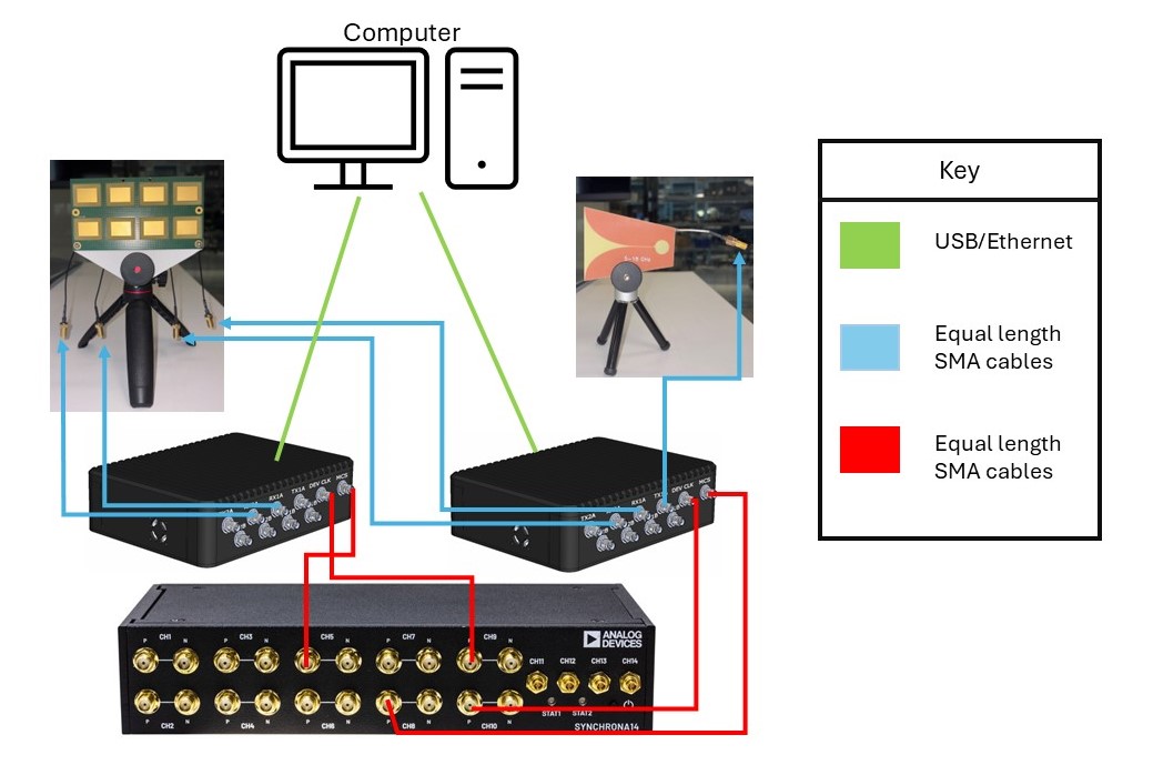
Hardware needed:
1x Main machine - its goal is to control and process data from others, through Ethernet(ssh)
2x jupiter_sdr + USB C Power supply (5V/3A, 9V/3A) if PoE is not available.
2x SD card(min 32G) for jupiter_sdr
1x Synchrona + ADD-ON Voltage Translation Board + 12V Power Supply
1x Ethernet Switch/Router (at least 5 ports)
4x Ethernet cables
3x Micro-USB (UART)
1x Beamforming array (OTA setup)
1x Transmit antenna (OTA setup)
9x SMA cables
4x SMA cables of same length and type for > 6GHz (splitter to Jupiter_sdr Rx)
4x SMA cables of same length and type for > 6GHz (Synchrona to Jupiter)
1x SMA cable (Jupiter_sdr Tx to splitter input)
Setting up MCS Pilot on Windows
Install Git
Install VS Code, or a similar IDE
If VS Code, these extensions are helpful: Python Debugger, Python Environments, Pylance, and Python
Open a new terminal
Make a directory for Jupiter MCS, then CD into that directory
Type:
git clone -b jupiter_sync_update_refactor https://github.com/analogdevicesinc/pyadi-iio.git
This will clone the appropriate dependencies
CD into pyadi-iio and follow the commands in the README
They are:
pip install . (once in pyadi-iio directory)pip install -r requirements_dev.txt
Get the additional requirements.txt file and put it in your Jupiter directory
While in the Jupiter directory on VS Code do
pip install -r .\requirements.txt
Go to jupiter_config.py
Change the IP addresses on lines 34-36
The primary Jupiter is the one with the TX signal
Now follow along with the walkthrough
Run the jupiter_sync_sine_example.py and jupiter_reload_profile_sync_sine_example.py
The reload profile sync example does a re-configure of the devices and then loads the previously stored calibration offsets/weights and it shows the sync is maintained.
You can run this example using the RF splitter and the OTA setup.
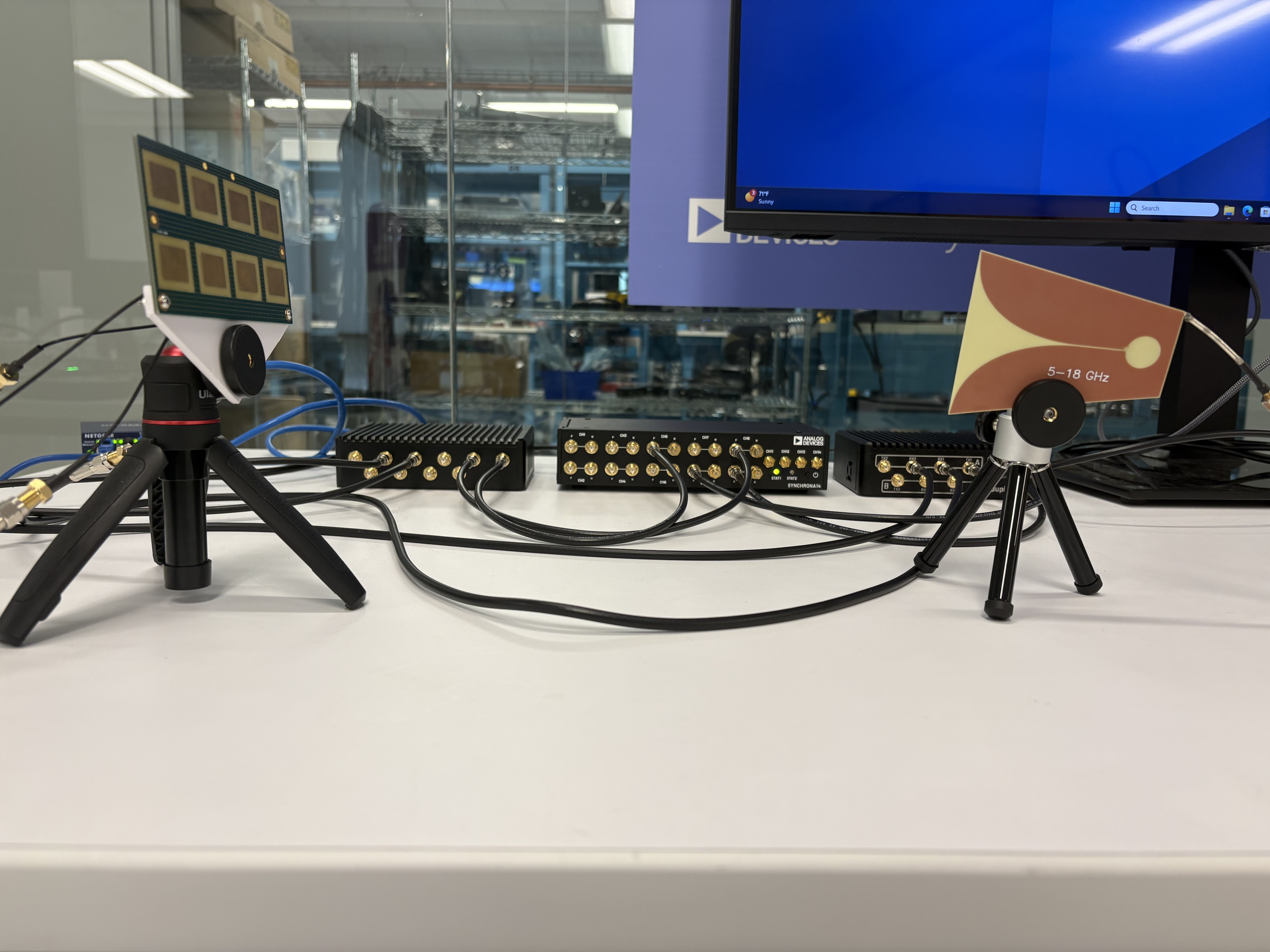
Note
In the PyADI-IIO repo, you can find two versions of this pilot: one that covers the OTA portion, and another that covers using an RF splitter. The setup procedure is the same for both.