ZED Quickstart
This guide provides quick instructions on how to set up the EVAL-AD5758SDZ on:
ZedBoard FMC LPC (via the EVAL-SDP-CK1Z / FMC-I-SDP interposer)
All the products described on this page include ESD (electrostatic discharge) sensitive devices. Electrostatic charges as high as 4000V readily accumulate on the human body or test equipment and can discharge without detection. Although the boards feature ESD protection circuitry, permanent damage may occur on devices subjected to high-energy electrostatic discharges. Therefore, proper ESD precautions are recommended to avoid performance degradation or loss of functionality. This includes removing static charge on external equipment, cables, or antennas before connecting to the device.
Using no-OS as software
Necessary files
Note
The no-OS setup boots from an SD card containing the boot image. The following file must be built before running the system.
The following file is needed for the system to boot:
Boot image:
BOOT.BIN
The boot image contains the FPGA bitstream and the no-OS application, and must be built manually from source:
Instructions on how to build the HDL bitstream can be found here: HDL User Guide with the AD5758 HDL project. More details at Build an HDL project.
Instructions on how to build the no-OS software can be found here: No-OS Build Guide with the AD5758 no-OS project.
Instructions on how to create the BOOT.BIN file: Build the boot image BOOT.BIN
Required Software
AMD Xilinx Vivado Design Suite (for the HDL build and creating BOOT.BIN)
ARM GNU Toolchain (for the no-OS build)
A UART terminal (PuTTY/Tera Term/Minicom, etc.) with baud rate 115200 (8N1)
SD card formatting tool (SD Card Formatter, balenaEtcher, or dd on Linux)
Git
Required Hardware
AMD Xilinx ZedBoard FPGA development board and its power supply (12V)
EVAL-AD5758SDZ evaluation board
EVAL-SDP-CK1Z (FMC-I-SDP) interposer board (required to connect the SDP-format board to the FMC connector)
SD card with at least 16GB of memory (formatted as FAT32)
24V bench-top power supply with connector cables (for the PVIN input)
Micro-USB cable (for UART communication)
Digital multimeter, precision current meter, or oscilloscope, plus a load resistor or current loop for the output range under test
More details as to why you need these can be found at Prerequisites.
Testing
Creating the setup
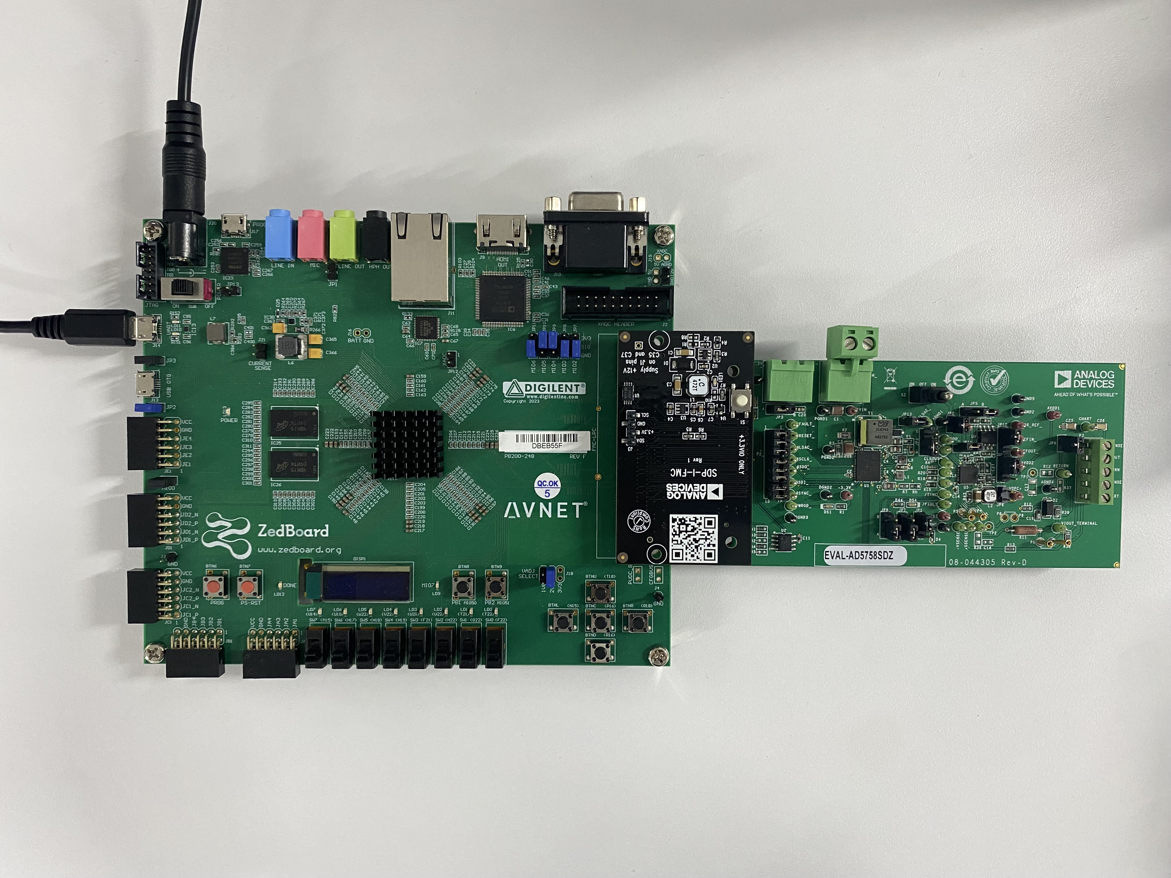
The setup connects the EVAL-AD5758SDZ to the ZedBoard via the EVAL-SDP-CK1Z (FMC-I-SDP) interposer.
Important
The EVAL-AD5758SDZ uses the SDP (system demonstration platform) format connector, which is not directly compatible with the ZedBoard’s FMC connector. The EVAL-SDP-CK1Z (FMC-I-SDP) interposer board is required to bridge between these two connector types.
Follow the steps in this order, to avoid damaging the components:
Get the ZedBoard.
Prepare the SD card:
Format the SD card as FAT32.
Copy the
BOOT.BINfile to the root directory of the SD card.Safely eject the SD card from your computer.
Configure the ZedBoard for SD card boot mode:
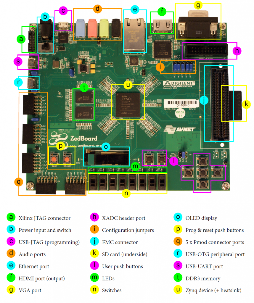
The BOOT mode jumpers (JP7-JP11) must be set for SD card boot mode as follows:
Table 1 Boot Mode Jumper Settings Jumper
Position
MIO6 (JP7)
GND
MIO5 (JP8)
GND
MIO4 (JP9)
3V3
MIO3 (JP10)
3V3
MIO2 (JP11)
GND
Note
SD card boot mode loads the boot image automatically from the SD card on power-up, eliminating the need for JTAG programming tools.
Install the EVAL-SDP-CK1Z (FMC-I-SDP) interposer board:
Align the interposer with the ZedBoard’s FMC LPC connector (J1).
Press firmly until fully seated; the interposer should sit flat against the ZedBoard.
Connect the EVAL-AD5758SDZ to the interposer:
Align the EVAL-AD5758SDZ’s SDP connector with the interposer’s SDP socket.
Press firmly until fully seated and secure.
Insert the SD card into the SD Card Interface Connector (J12).
Connect the micro-USB cable from the ZedBoard’s USB-UART port (J14) to your PC. This provides the UART communication interface.
Connect the output measurement equipment:
Connect a digital multimeter, current meter, or oscilloscope (with a suitable load) to the evaluation board’s output terminals.
Connect the power supplies, but do not turn them on yet:
Plug the 12V power supply into the ZedBoard’s power input connector (J20).
Connect the 24V bench-top supply to the PVIN connector of the EVAL-AD5758SDZ, keeping the supply output off.
Power on the system:
Turn on the power switch on the ZedBoard.
Once the ZedBoard is running, turn on the 24V supply to the EVAL-AD5758SDZ.
The system boots automatically from the SD card and the no-OS application starts.
Boot messages
The following is what is printed in the serial console, after you have connected to the proper ttyUSB or COM port at 115200 baud, 8N1.:
ad5758 successfully initialized
Success
Verifying the setup
Once the No-OS application is running, the UART terminal displays the initialization output.
Note
A digital multimeter (DMM) can be used to measure the DAC output voltage
across the VI_OUT and RETURN pins on the P3 connector. Expected
output voltage is 5V based the No-OS project.
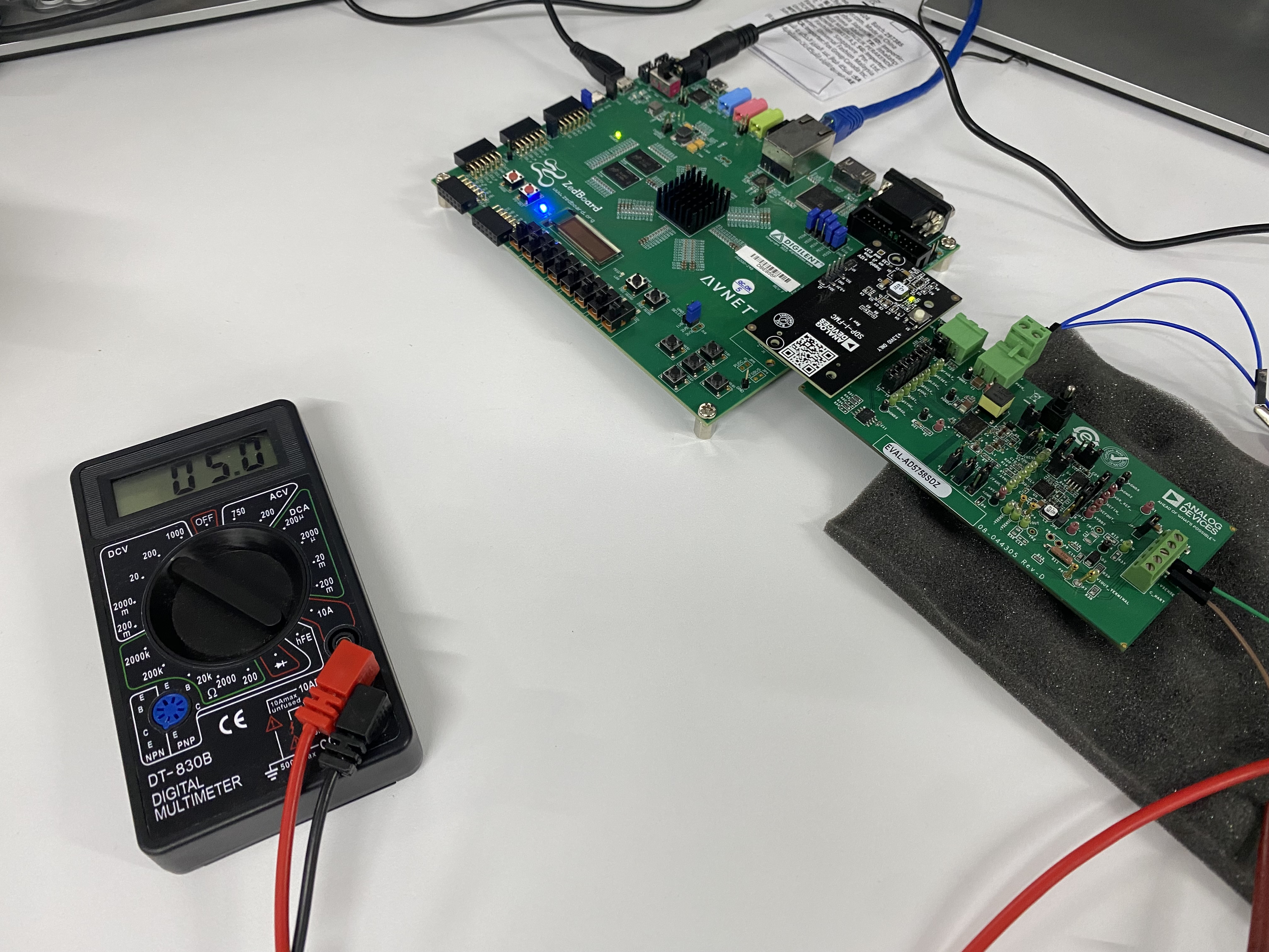
Figure 3 EVAL-AD5758SDZ + FMC-I-SDP + ZedBoard Sample Output Measurement