EVAL-ADPAQ3029 - Hardware setup
The EVAL-ADPAQ3029 evaluation kit mainly consists of below 2 parts.
1. ADPAQ Development module
The ADPAQ development module, allows us to build applications on ADuCM3029 microcontroller from Analog Devices that is compatible with the Moduware development platform. The ADuCM3029 has the following features/resources-
ARM Cortex-M3 processor with a Memory Protection Unit (MPU)
Operating frequency upto 26 MHz with serial wire debug interface
256 KB of embedded flash memory with Error Correcting Code (ECC)
64 KB of configurable system SRAM with parity
Hardware cryptographic accelerator supporting AES-128, AES-256, and SHA-256
Three SPI interfaces
I2C and UART interfaces
Serial Port (SPORT) for natively interfacing with converters and radios
Programmable GPIOs
3 general-purpose timers with PWM support
RTC and FLEX_RTC with SensorStrobe and time stamping
12-bit, 8 channel SAR ADC
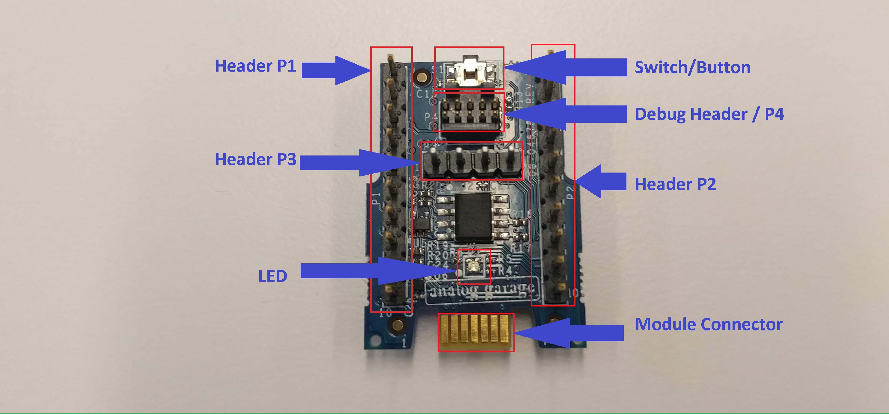
The ADPAQ module is as shown in the figure below. It mainly consists of 3 evaluation headers namely P1, P2 and P3, a debug connector, an ADT7410 IC (it is a temperature sensor) and a Moduware connector. The schematics of the ADPAQ module can be viewed from the link. It gives more details about the hardware of the module.
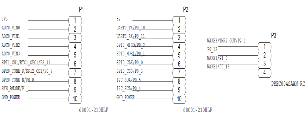
The pin description of the evaluation headers is as shown below:
2. Moduware gateway (Mini-Dev board)
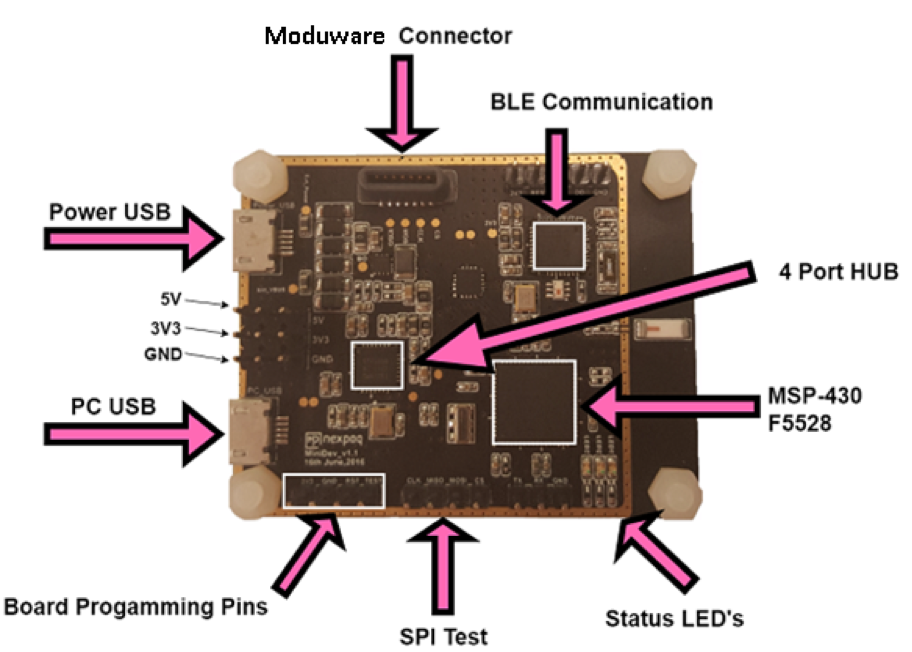
The gateway used in this setup is the Mini Dev Board.
The Mini-dev board communicates with the module via SPI and it communicates with the mobile application via BLE (Bluetooth Low Energy).
The Mini-Dev Board is powered on by connecting one end of the USB cable to the Power USB slot on the Mini-dev Board and the other end to the computer.
The Mini-Dev Board is based on MSP-430 (Micro Controller) and has a BLE IC.
The Mini-dev Board has a Moduware connector slot where the module has to be inserted. The SPI communication between the module and the Mini-Dev Board takes place through these pins.
Setup
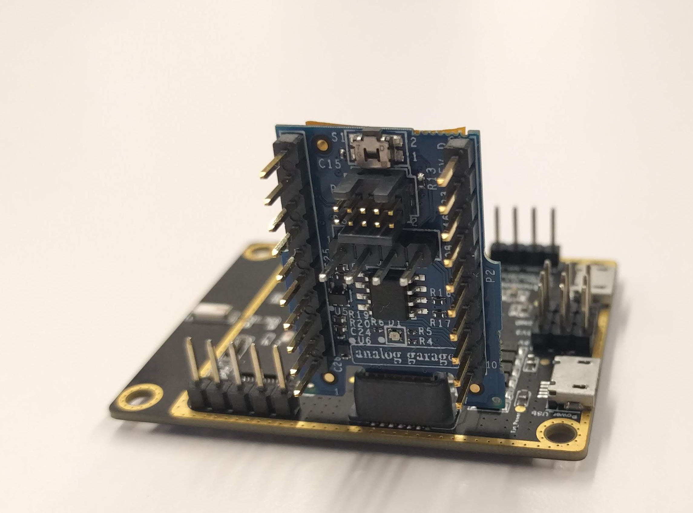
The ADPAQ module is inserted onto the gateway with the pins facing inward as shown in the image.
Power the gateway by connecting the USB cable to the Power USB slot.
Once the hardware setup is complete, setting up software toolchain is explained here.
In addition to above setup, in order to debug/flash the firmware, debugger (EVAL-ADPAQ3029EBZ-DBG) must be connected between PC and ADPAQ Dev module.
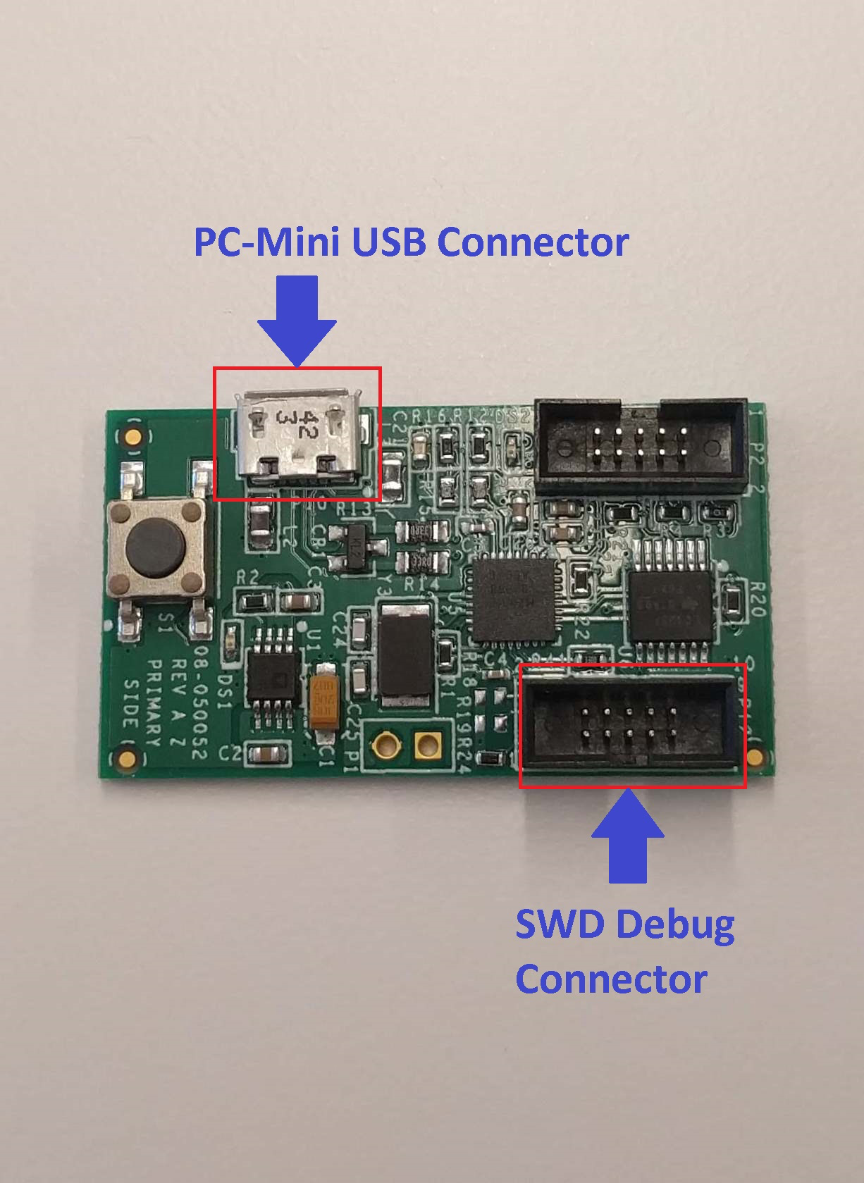
The ADPAQ module is connected to the debugger via a 10 pin arm debugger cable and the debugger is then powered on through the Power USB port as shown in the figure below.
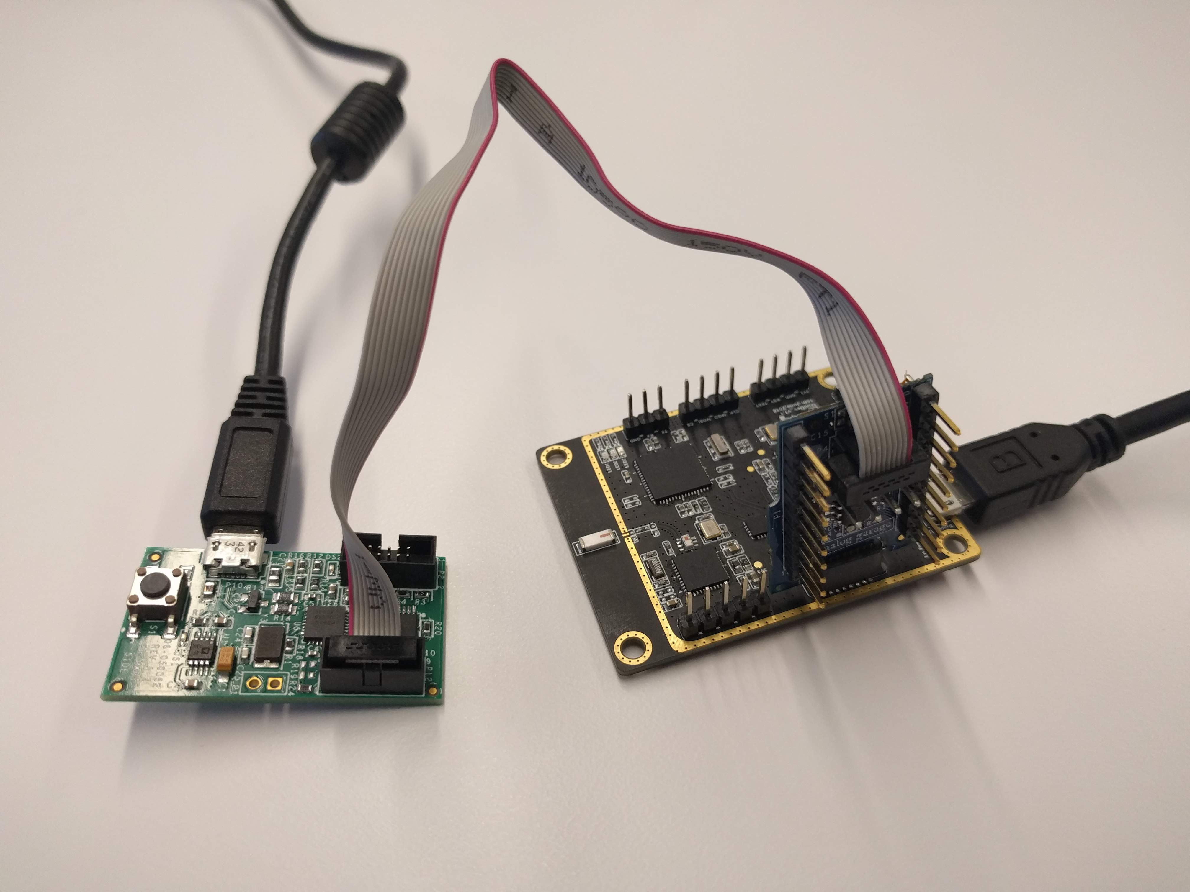
Once the hardware is set up as described above, the device appears as
DAPLINK.
Important
Make sure that the gateway is powered first with the ADPAQ module already inserted on it and then connect it to the debugger. Otherwise the device manager shows MAINTENANCE instead of DAPLINK.