DE10-Nano Quickstart
This guide provides quick instructions on how to set up the AD57xx on:
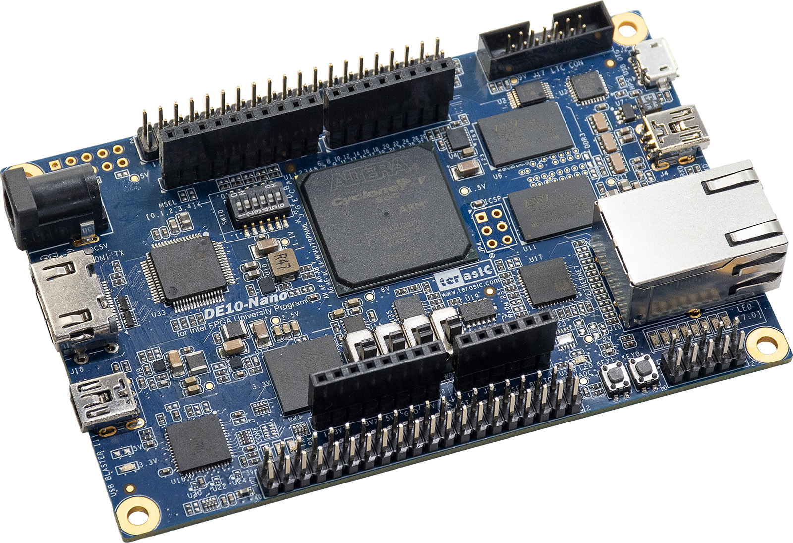
DE10-Nano on Arduino shield connector
All the products described on this page include ESD (electrostatic discharge) sensitive devices. Electrostatic charges as high as 4000V readily accumulate on the human body or test equipment and can discharge without detection. Although the boards feature ESD protection circuitry, permanent damage may occur on devices subjected to high-energy electrostatic discharges. Therefore, proper ESD precautions are recommended to avoid performance degradation or loss of functionality. This includes removing static charge on external equipment, cables, or antennas before connecting to the device.
Using Linux as software
Necessary files
The following files are needed to boot the system:
system_top.rbf, HDL bitstream built from Build an HDL projectu-boot-with-spl.sfp, SPL and U-Boot bootloadersocfpga.dtb, compiled device tree blobzImage, the Linux kernel image
Note
Pre-built files for this reference design are not yet available. The bitstream must be built manually following the AD57XX_ARDZ HDL project build documentation. For general HDL build instructions, see Build an HDL project.
HDL source: /projects/ad57xx_ardz/de10nano
Copy the built files to the BOOT partition of the SD card.
The Kuiper boot flow loads the bitstream automatically via the
extlinux boot sequence.
Required Software
SD Card 16GB imaged with Kuiper (provides the root filesystem; the HDL bitstream must be built separately as described above)
A UART terminal (Putty/Tera Term/Minicom, etc.) with baud rate 115200 (8N1)
Required Hardware
DE10-Nano FPGA board
5V/2A wall power supply with barrel jack (comes with DE10-Nano)
Mini-USB to USB Type A cable (comes with DE10-Nano)
EVAL-AD5780ARDZ/ EVAL-AD5781ARDZ/ EVAL-AD5791ARDZ evaluation board
Voltage reference daughter board (EV-ADR445-REFZ included with evaluation kit)
Class 10 16GB SD Card
LAN cable (Ethernet)
DMM or oscilloscope for measuring DAC output voltage
More details as to why you need these can be found at Prerequisites.
Testing
Creating the setup
AD57xx/DE10-Nano
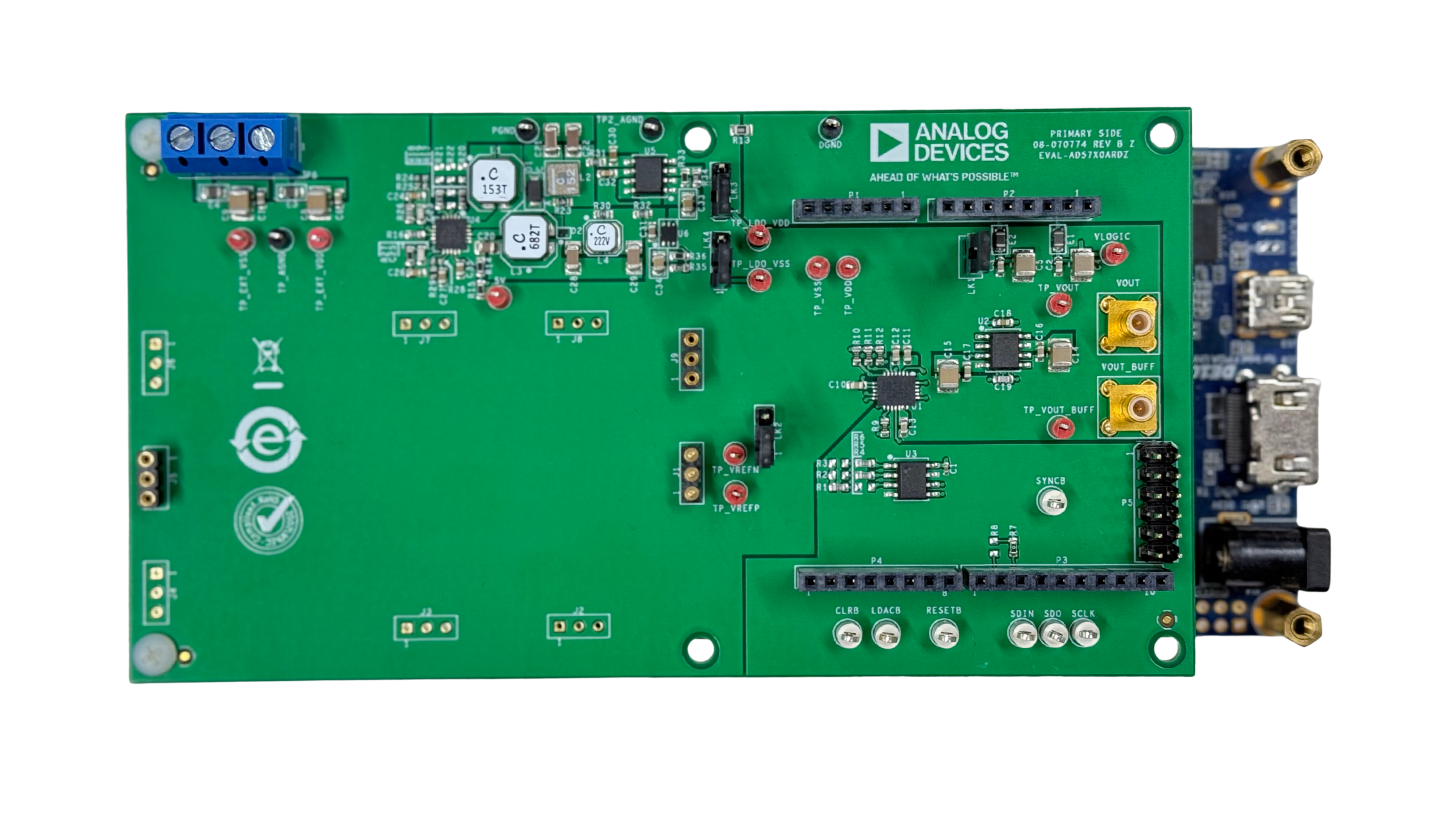
In the following example, we will prepare the evaluation setup by connecting the AD57xx board to the DE10-Nano and configuring it to produce a DAC output.
Follow the steps in this order, to avoid damaging the components:
Get the DE10-Nano
Verify the FPGA Configuration Mode Switch (S10) is configured properly:
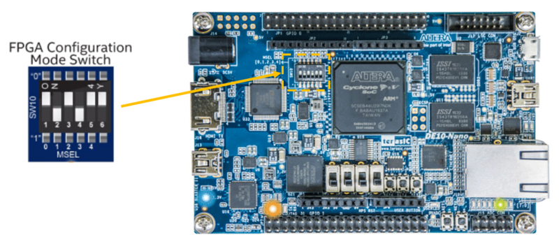
The DE10-Nano comes ready to use out of the box, but it is important to double check that the FPGA Configuration Mode Switch (S10) is set correctly. If more information is needed, check out the DE10-Nano Getting Started Guide.
Prepare the SD card:
Validate, Format, and Flash the SD Card following the Use Kuiper Image guide.
Copy the built
system_top.rbf,socfpga.dtb, andzImageto theBOOTpartition of the SD card.
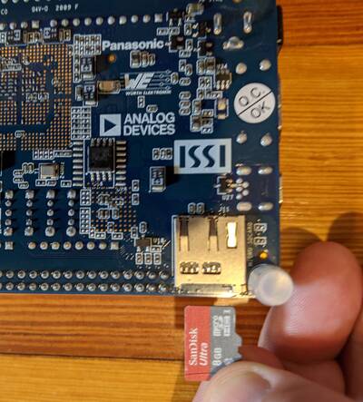
Insert the microSD card into the DE10-Nano card slot
Plug-in an Ethernet cable from your router/switch to the Ethernet port on the FPGA board
Info
If you don’t have a network available and want to stream data directly from the Ethernet port of the DE10-Nano to the Ethernet port of your PC, that is still possible, but requires some extra configuration. Please see the [Wiki] Network Configuration page for complete details.
Ensure the voltage reference daughter board (EV-ADR445-REFZ or equivalent) is connected to the J1, J4, and J9 connectors on the evaluation board.
Using the Arduino pins, plug the EVAL-AD5780ARDZ/ EVAL-AD5781ARDZ/ EVAL-AD5791ARDZ on top of the DE10-Nano
Connect a DMM or oscilloscope to the VOUT or VOUT_BUFF connector on the evaluation board to measure the DAC output voltage.
Connect the UART port of DE10-Nano to a PC via Mini-USB cable (DO NOT power on the device yet)
Note
A driver for the board should automatically be detected and installed on your PC. If this does not happen, you may need to manually install the driver. Here is a link to the UART Serial Driver.
Plug the 5V/2A power supply into the wall outlet and power up the setup
Observe Kernel and serial console output messages on your terminal
Boot messages
The following is what is printed in the serial console, after you have connected to the proper ttyUSB or COM port:
Useful commands for the serial terminal
The below commands are to be run in the serial terminal connected to the FPGA.
Login Information
user: analog password: analog
To find out the IP of the FPGA board, run the following command and take the IP specified at “eth0 inet”:
~$
ifconfig
To see the IIO devices detected, run:
~$
iio_info | grep iio:device
To power off the system, run the following command, and wait for the final message to be printed, then power off the FPGA board from the switch as well.
~$
poweroff
To reboot the system, run:
~$
reboot
Important
Even though this is Linux, this is a persistent file system.
Care should be taken not to corrupt the file system – please
shut down things, don’t just turn off the power switch.
Depending on your monitor, the standard power off could be
hiding. You can do this from the terminal as well with
sudo shutdown -h now or the above-mentioned command
for powering off.
Scopy
Important
Make sure to download/update to the latest version of Scopy.
Scopy can be used to control the DAC output voltage through the IIO plugin. Connect to the board via its IP address, then use the DAC channel controls to set the desired output code or voltage.
IIO Oscilloscope
Important
Make sure to download/update to the latest version of IIO Oscilloscope.
Once done with the installation or an update of the latest IIO Oscilloscope, open the application. The user needs to supply a URI which will be used in the context creation of the IIO Oscilloscope.
Press
Refreshto display available IIO Devices and pressConnect.After the board is connected and a channel is enabled, hit the play button. Then the data capture window can be seen like in the shown picture.