Linux User Guide
This guide describes how to connect the EVAL-ADIN1320FMCZ to a Zedboard running Linux, and use the two on-board ADIN1320 PHYs as PHYs for the network interfaces.
Hardware requirements
For this setup you will need the following boards or hardware accessories:
EVAL-ADIN1320FMCZ
Cat5+ Ethernet cable(s)
A 1000BASE-X or 100BASE-FX capable SFP module (optional, for testing fiber media on Port 0)
SD card
Eval board setup
The EVAL-ADIN1320FMCZ plugs directly into the Zedboard’s FMC LPC connector; no jumper wires are required.
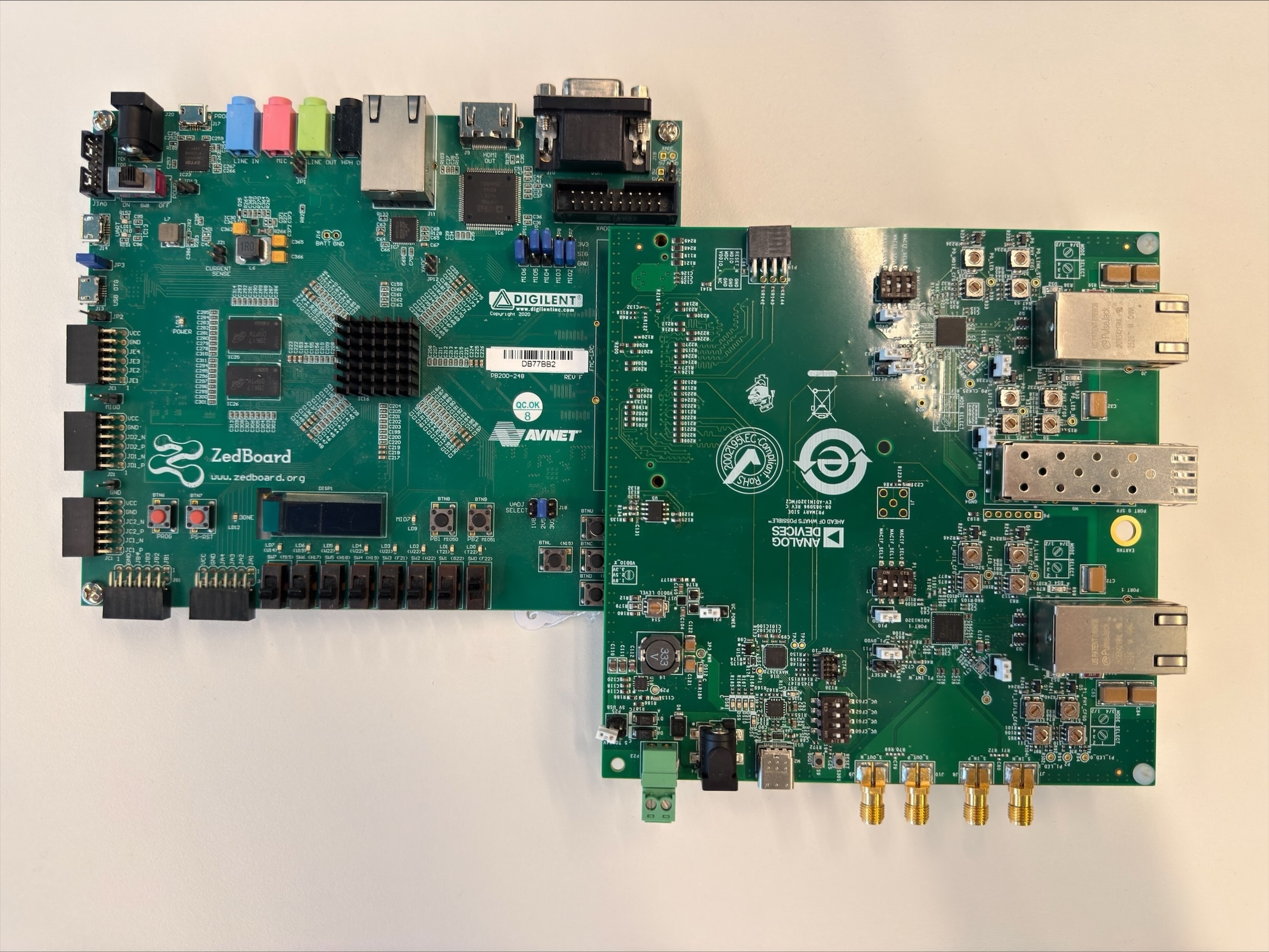
Figure 1 EVAL-ADIN1320FMCZ connected to the Zedboard’s FMC LPC connector
The board carries two ADIN1320 PHYs, Port 0 (P0) and Port 1 (P1):
Port 0 supports either Copper (RJ45) or Fiber (SFP cage) media.
Port 1 supports Copper (RJ45) media only.
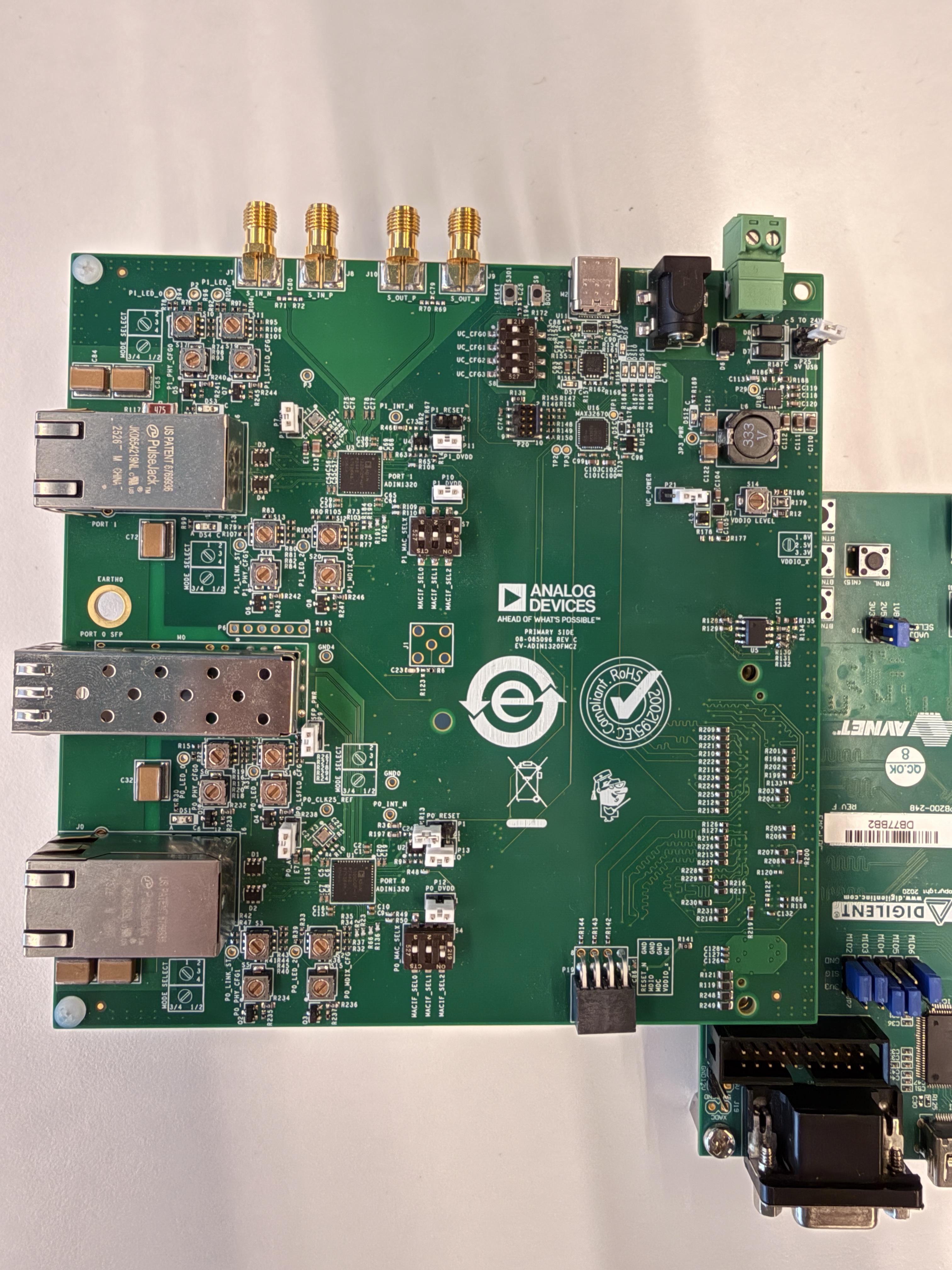
Both PHYs are managed over a single MDIO bus, driven by GEM1, that is shared
between Port 0 (address 0x0) and Port 1 (address 0x8); see the
mdio node under &gem1 in the devicetree. The MAC interface mode
(RGMII) is not configured over MDIO, though: it is fixed by hardware
strapping on the board, and this is the only mode supported by this
revision of the guide. The values below are the ADIN1320 hardware
configuration pin values (see the ADIN1320 datasheet, “Hardware
Configuration Pins” section) required for this mode and are provided as a
reference of what must be configured; no user action is needed to reproduce
them.
Important
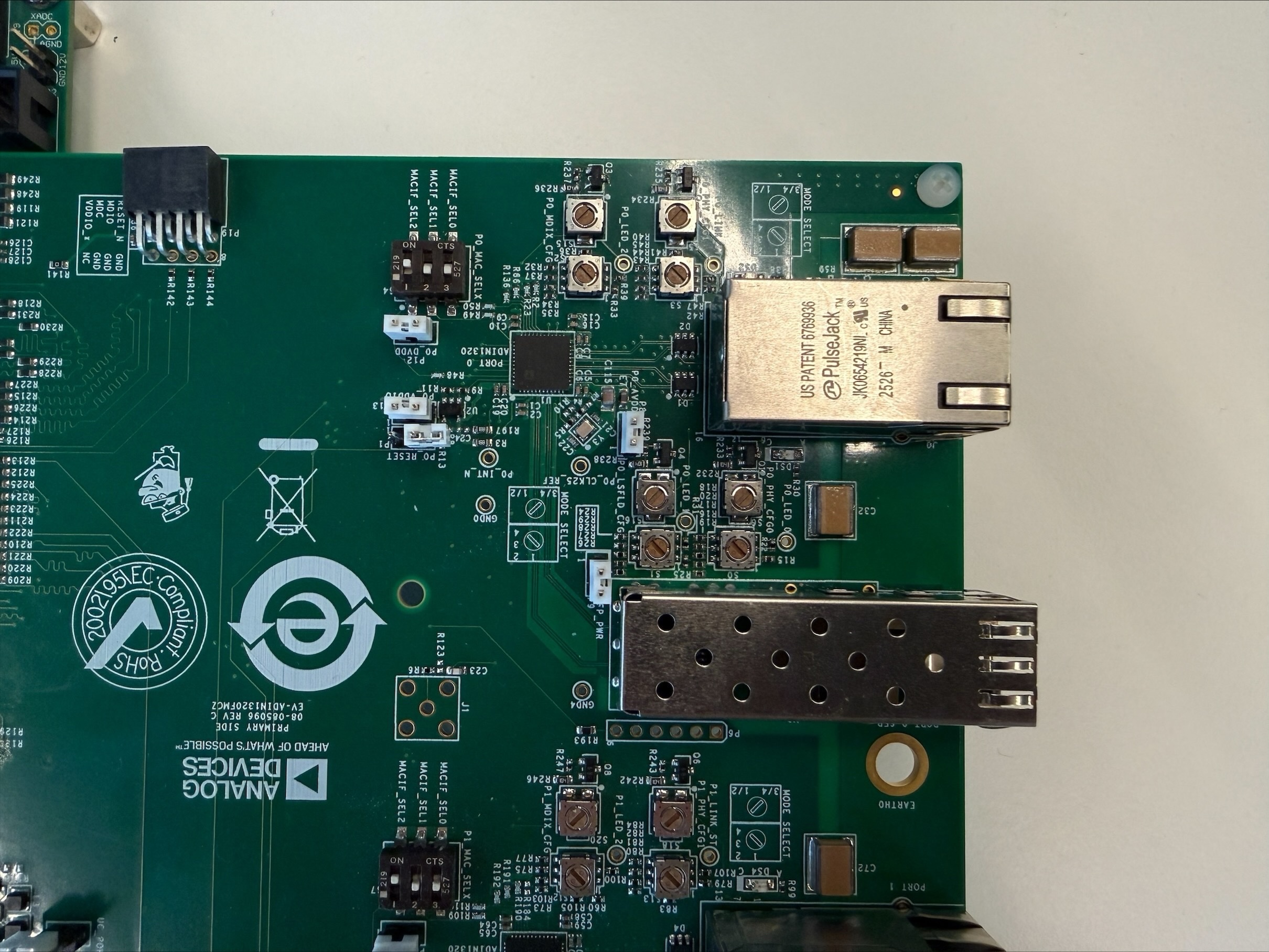
To use an SFP module on Port 0 instead of the RJ45 connector, insert it into the M1 cage, and short the M1 (SFP_PWR) jumper to power the SFP module.
Important
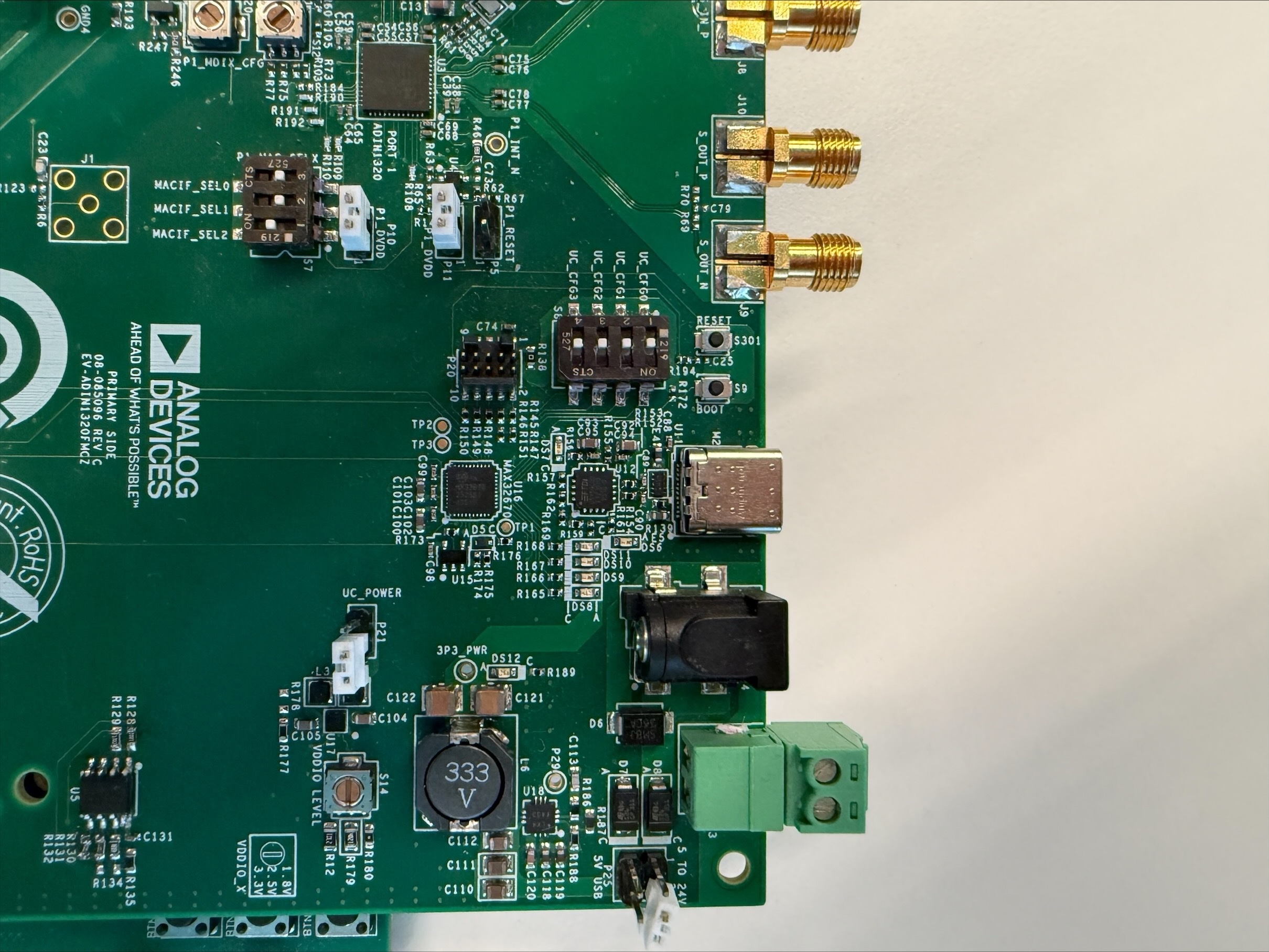
Jumper P21 (uC_POWER) must be disconnected. This jumper supplies power to the on-board MCU, which can alternatively drive the MDIO bus instead of the FPGA over the FMC connector. Leaving P21 connected powers the MCU and creates a conflict with FMC/FPGA-based MDIO control.
Important
Jumper P25 selects between two power sources (USB or an external 5 V-24 V supply). The FMC connector supplies power through a separate path unaffected by P25, so P25 can be left open when powering the board through the FMC connector.
Important
On Rev C boards, the on-board EEPROM (U5) shares the same I2C bus as
the SFP cage and is strapped to address 0x50, which collides with the
I2C address used by the EEPROM on SFP modules. This prevents the host
from reading the SFP module’s EEPROM correctly. To use an SFP module on
Rev C boards, disconnect pin 8 (VDD) of U5 – e.g. by lifting the pin or
cutting its trace – or desolder U5 entirely.
SD card setup
Flash a Linux distribution image to an SD card. Kuiper Linux is recommended, since it contains everything (kernel and HDL images, devicetree, rootfs) needed to get started.
Download the Kuiper Linux v2.0.0 image.
Extract the archive and flash the
.imgfile to the SD card, for example with Balena Etcher.Download the EVAL-ADIN1320FMCZ artifacts archive, which contains the
uImage,BOOT.BIN, anddevicetree.dtbbuilt for this reference design.Extract the artifacts archive and copy
uImage,BOOT.BIN, anddevicetree.dtbonto the BOOT partition of the SD card (the FAT partition mounted when the card is plugged into a PC), overwriting the files already present there.
Insert the SD card into the Zedboard and boot:
Plug the EVAL-ADIN1320FMCZ into the Zedboard’s FMC LPC connector (with the board powered off).
Connect the PC to the Zedboard (J14) using a micro USB cable.
Connect the power adapter.
Power on the board using the SW8 switch.
Connect using a serial terminal emulator (e.g.
tiofor Linux or PuTTY for Windows). The UART settings are 115200/8N1. TheCR after every LFoption may need to be enabled manually.Press enter if no boot log appears, since the board may have already booted.
Power off the board once boot is confirmed.
Testing the EVAL-ADIN1320FMCZ
With the EVAL-ADIN1320FMCZ already connected to the Zedboard’s FMC LPC connector, connect an Ethernet cable to Port 1’s RJ45 connector (or a Cat5+ cable/SFP module to Port 0). Power on the board and check that the link is up:
~$
ip a
Two network interfaces should be present, one for each ADIN1320 PHY (Port 0
on GEM1, Port 1 on GEM0). Once a link partner is connected, the corresponding
interface should show as UP,LOWER_UP. Ethernet traffic can now be passed
through the network interface.
At this point, only the generic Ethernet PHY driver is being used. Unless
some of the ADIN13xx specific features are needed (frame checker counters,
MDI/MDIX settings via ethtool), the ADIN1320 does not require a
device-specific Linux driver — it is supported by the mainline adin PHY
driver.
Testing scenarios
The following scenarios exercise the ADIN1320 PHY and its Linux support.
Examples use eth0; substitute the interface name that corresponds to the
port under test (Port 0 or Port 1).
Important
ethtool and phytool are not
installed by default on the Kuiper rootfs. Install ethtool with:
~$
sudo apt update && sudo apt install -y ethtool
phytool is not packaged; build and install it from source:
~$
sudo apt install -y git build-essential
~$
git clone https://github.com/wkz/phytool.git
~$
cd phytool
~/phytool$
make
~/phytool$
sudo cp phytool mdio /usr/local/bin/
Link and traffic verification
~$
ip a
Confirm the interface is UP,LOWER_UP.
To verify frame transmission, assign a static IP address to the interface and ping a link partner with a known, already-configured static IP on the same subnet:
~$
ip addr add 192.168.97.40/24 dev eth0
~$
ping 192.168.97.10
After passing traffic, check that both RX and TX packet counters increment:
~$
ip -s link show eth0
If only one side increments, this usually points to a MAC/PHY configuration mismatch (speed, duplex, or interface mode).
Copper and fiber media testing
Copper: connect a Cat5+ cable between Port 0 or Port 1’s RJ45 connector and a link partner, and verify link-up as above.
Fiber: insert a 1000BASE-X capable SFP module into Port 0’s SFP cage, and verify link-up the same way. Fiber media is only available on Port 0.
Important
Troubleshooting: on U1 revisions of the ADIN1320, the PHY sometimes fails to detect a link with the PHY on the SFP module. If fiber link-up does not occur, work around this by either:
Inserting the SFP module before powering on/resetting the board, so it is already in place when the ADIN1320 comes out of reset during Linux boot; or
Connecting a Cat5+ cable to Port 0’s RJ45 connector first, waiting for copper link-up, then disconnecting the cable and inserting the SFP module.
Link speed and duplex configuration
~$
ethtool -s eth0 speed 10 duplex full autoneg off
~$
ethtool -s eth0 speed 100 duplex full autoneg off
~$
ethtool -s eth0 autoneg on
MDI/MDIX configuration
~$
ethtool -s eth0 mdix auto # auto-mdix, MDI preferred by default
~$
ethtool -s eth0 mdix off # MDI mode manual
~$
ethtool -s eth0 mdix on # MDIX mode manual
PHY statistics (frame checker counters)
~$
ethtool --phy-statistics eth0
Important
Do not confuse PHY statistics with MAC statistics, available separately
via ethtool --statistics eth0 or ethtool -S eth0.
PHY register access
Low level register access can be done with phytool, useful as a sanity check (e.g. reading the PHY ID):
~$
phytool read eth0/0/0x2
~$
phytool read eth0/0/0x3
Important
phytool can only access registers via Clause 22. Clause 45 is not
supported by the PHY driver. Registers above address 0x1f are MMD
registers and require the indirect access sequence via registers 0x10
and 0x11.
Compiling the Linux driver
Important
The mainline adin PHY driver (CONFIG_ADIN_PHY) does not yet
support the ADIN1320. Until support is merged upstream, use the adin
driver from the ADI Linux kernel fork’s release/adin1320 branch (based on Linux 6.12), which also contains
the devicetree for this reference design.
Set up the cross compile environment for Zynq (see the
Linux kernel build guide for toolchain options),
then clone the release/adin1320 branch and build the kernel, modules, and
devicetree:
~$
git clone https://github.com/analogdevicesinc/linux.git \
            --branch release/adin1320 --single-branch --depth=10 \
            -- linux
~$
cd linux
~/linux$
export ARCH=arm
~/linux$
export CROSS_COMPILE=arm-linux-gnueabihf-
~/linux$
make zynq_xcomm_adv7511_defconfig
~/linux$
make -j12 UIMAGE_LOADADDR=0x8000 uImage
~/linux$
make xilinx/zynq-zed-adin1320fmcz-rgmii.dtb
~/linux$
make modules -j12
This produces arch/arm/boot/uImage and
arch/arm/boot/dts/xilinx/zynq-zed-adin1320fmcz-rgmii.dtb. Copy them onto
the SD card’s BOOT partition, renaming the devicetree to devicetree.dtb:
~$
cp arch/arm/boot/dts/xilinx/zynq-zed-adin1320fmcz-rgmii.dtb /media/$USER/BOOT/devicetree.dtb
~$
cp arch/arm/boot/uImage /media/$USER/BOOT/uImage
Then follow the same process described in the Testing the EVAL-ADIN1320FMCZ section above to validate the board with the new kernel.