AD-BMSE2E3WLC-SL
Low-cost Battery Management System Reference Design for E2W/E3W Applications
Overview
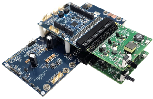
The AD-BMSE2E3WLC-SL is a cost-competitive system-level reference design for medium to high-end Battery Management System (BMS) applications in Electric 2-Wheeler (E2W) and Electric 3-Wheeler (E3W) markets. Operating within a voltage range of 36V to 96V and supporting currents up to 100A, this reference design leverages the automotive-grade ADBMS1816W integrated circuit with comprehensive cell and current sensing capabilities.
The system features built-in charge/discharge circuitry supporting both high-side and low-side current sensing. It includes a compatible microcontroller board that handles computational operations required for BMS functionality and provides USB-to-SPI communication for GUI interaction.
The modular, stackable design offers flexibility to utilize customer-preferred MCUs through standard Arduino/Feather board form factors.
The reference design also includes open-source firmware example codes and a comprehensive GUI, enabling rapid prototyping and evaluation of BMS solutions.
Features
Wide Range BMS System
can operate from 36V to 96V, can handle currents up to 100A
Simplified E2W/E3W AD-BMSE2E3WLC-SL baseboard + EVAL-ADBMS1816WLC daughterboard configuration
Battery Chemistry Compatibility
Supports multiple battery chemistries: Ni-MH, Li-ion, LiFePO4, Sodium-ion
System Integration
Plug-and-play integration
MCU-agnostic design for easy integration into existing systems
Flexible topology support: Centralized, Distributed, and Modular configurations
Monitoring Capabilities
Cell voltage accuracy: ±3.6mV
Temperature monitoring: Up to 8 sensors
SoC/SoH Coulomb counting
High-side and low-side current sensing
Vehicle State Management
E2W/E3W vehicle state condition readiness
Support for Driving, Charging, Parking, and Fault states
Connectivity and Software
Daisy-chaining ready for multi-board configurations
Comprehensive GUI compatible with any PC/laptop
Integrated firmware and GUI software suite
Real-time monitoring, diagnostics, and data plotting capabilities
Open-source BMS example codes provided
Applications
Medium to High Performance Electric and Hybrid 2-Wheeler and 3-Wheeler Vehicles
Light Electric Vehicles
BMS Battery Research and Development
Adaptive Battery Type System Monitoring
Portable Energy Storage Systems
System Architecture
Theory of Operation
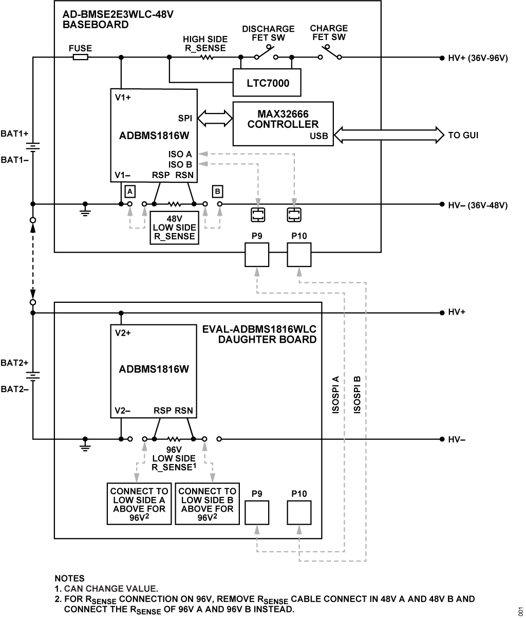
The AD-BMSE2E3WLC-SL system combines battery cell monitoring, current sensing, temperature monitoring, charge/discharge control, and host communication into a scalable platform supporting battery packs from 36V to 96V and up to 32 series-connected cells.
At the core of the system is the ADBMS1816W battery monitoring IC, which continuously measures individual cell voltages and temperature sensor inputs. Two ADBMS1816W devices are used in a daisy-chain configuration to support up to 32 cells while maintaining high measurement accuracy and reducing communication wiring complexity through the isoSPI interface. Measured battery parameters are transmitted to the host microcontroller for processing and display.
The MAX32666FTHR microcontroller serves as the system controller and communication gateway. It collects measurement data from the battery monitor devices, executes battery management functions such as SOC and SOH calculations, manages system operating states, and communicates with the PC-based GUI through a USB connection. The MCU-agnostic hardware architecture allows alternative processor platforms to be integrated through the Arduino and Feather-compatible interfaces.
Battery pack current is monitored through precision shunt resistors located on the baseboard. The measured current information is used for coulomb counting, charge/discharge monitoring, and battery protection functions. The system supports both high-side and low-side current-sensing topologies, enabling flexibility for different battery pack architectures.
Charge and discharge path control is implemented using external MOSFETs driven by the LTC7000 gate driver. Based on battery conditions and operating state, the BMS can enable or disable power delivery to the load or charger. This allows implementation of vehicle operating modes such as Driving, Charging, Parking, and Fault conditions while protecting the battery pack from abnormal operating events.
For evaluation purposes, the AD-BMSE2E3WLC-SL can be connected to DC2472A battery emulators, allowing users to safely simulate battery cell voltages and observe system behavior through the graphical user interface. The GUI provides real-time monitoring of cell voltages, stack voltage, current, temperature measurements, and system status, facilitating rapid development and validation of battery management algorithms.
This modular architecture enables rapid prototyping, evaluation, and customization of battery management solutions while providing a foundation that can be adapted for E2W, E3W, and other light electric vehicle applications.
Specifications
Parameter |
Min |
Typical |
Max |
Unit |
Notes |
|---|---|---|---|---|---|
System |
|||||
Total Vin+ Supply Voltage |
30 |
100 |
V |
Input voltage supply from battery |
|
Battery Emulator Output |
30 |
100 |
V |
Safe output voltage from Battery Emulator |
|
Discharge Current |
40 |
100 |
A |
Current rating at discharge mode |
|
Charge Current |
0.3 |
40 |
70 |
A |
Current rating at charge mode |
Charge Voltage Input |
96 |
V |
|||
Discharge Voltage Output |
36 |
96 |
V |
Regulated voltage range |
|
FET Driver Charge Input |
5 |
V |
From ADBMS1816W GPIO |
||
FET Vgs Range |
-20 |
20 |
V |
From ADBMS1816W GPIO |
|
FET Rds(on) |
4.8 |
mΩ |
From ADBMS1816W GPIO |
||
ADBMS1816W Cell Monitor |
|||||
VREG Supply |
4.5 |
5 |
5.5 |
V |
|
VREF1, VREF2 |
3 |
3.3 |
V |
Supply to internal ADCs |
|
VRES/VDD |
4.5 |
5 |
5.5 |
V |
|
Operating Temperature |
-40 |
125 |
°C |
||
CPIN Input Range |
-2.5 |
5.5 |
V |
||
Cell Count |
1 |
32 |
Minimum 17 cells to initiate daisy chain |
||
Drive Voltage Range |
-0.3 |
6 |
V |
Relative to each cell monitor V- |
|
VP Range |
16 |
80 |
V |
||
VREG Pack Monitor |
4.5 |
5 |
5.5 |
V |
|
MAX32666 Microcontroller |
|||||
MCU Supply Voltage from BMS |
3.3 |
5.5 |
V |
||
MCU I/O Supply (1.8V) |
1.6 |
3 |
V |
||
MCU VDD Supply |
3.3 |
5.5 |
V |
||
MCU Supply (1.2V) |
1.1 |
1.35 |
V |
||
MCU Supply (1.0V) |
0.9 |
1.2 |
V |
Package Contents
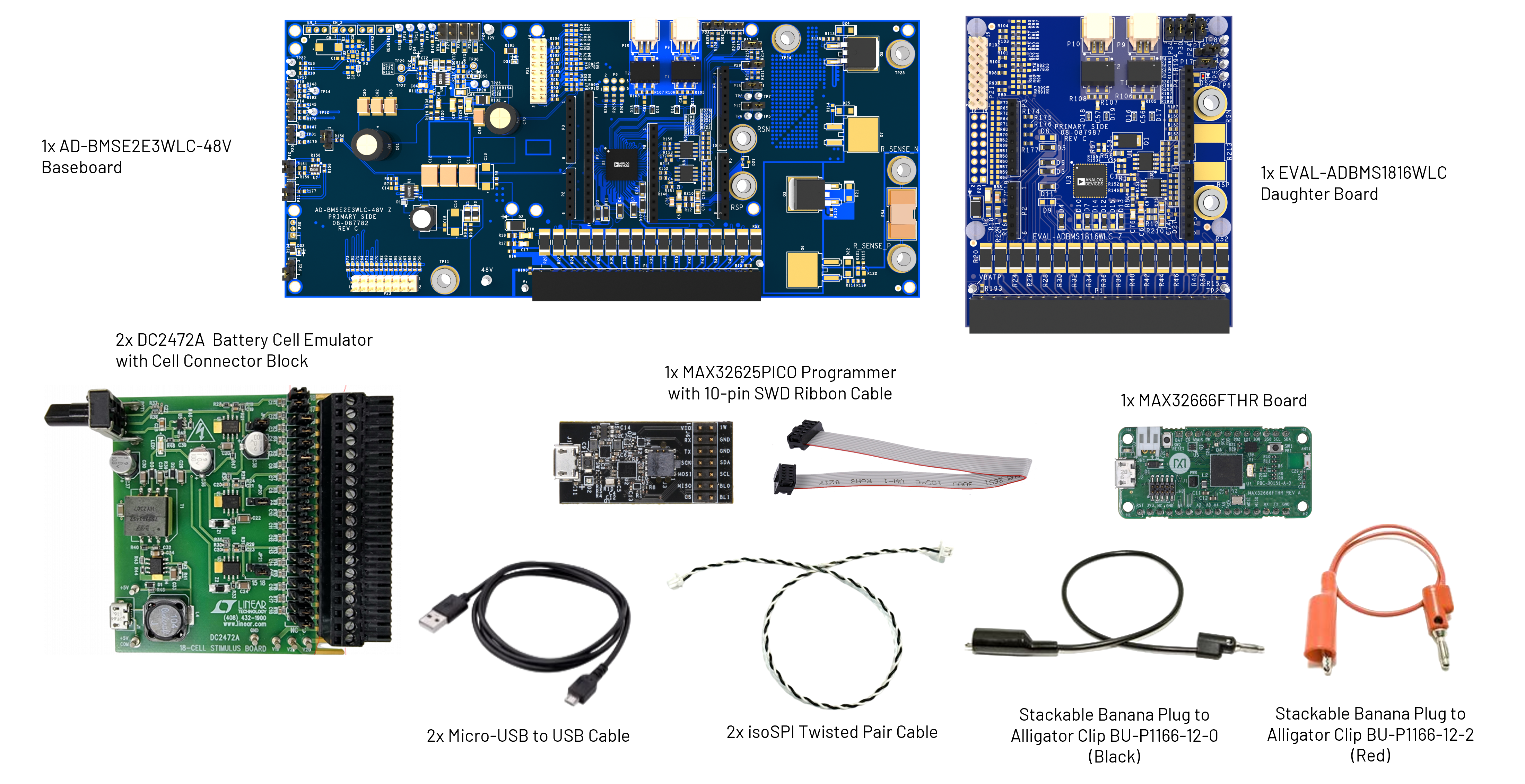
Upon purchase, the AD-BMSE2E3WLC-SL comes complete with 1 baseboard, 1 daughter board, and 1 microcontroller.
However, customers also have the option to avail of the components individually as intended for their application development.
1x AD-BMSE2E3WLC-48V Baseboard
1x EVAL-ADBMS1816WLC Daughter Board
1x MAX32666FTHR Microcontroller Board
2x DC2472A Battery Emulator
1x MAX32625PICO Programmer with 10-pin SWD Ribbon Cable
2x isoSPI Twisted Pair Cable
2x USB Cable for PC Connection
Stackable Banana Plug to Alligator Clip BU-P1166-12-0 (Black)
Stackable Banana Plug to Alligator Clip BU-P1166-12-2 (Red)
User Guides
Proceed to the following pages for detailed information on how to use the AD-BMSE2E3WLC-SL reference design:
Resources
Design & Integration Files
Download
AD-BMSE2E3WLC-SL Design Support Package
Schematic
PCB Layout
Bill of Materials
Allegro Project
Help and Support
For questions and more information, please visit the EngineerZone Support Community.