Hardware Guide

Components and Connections

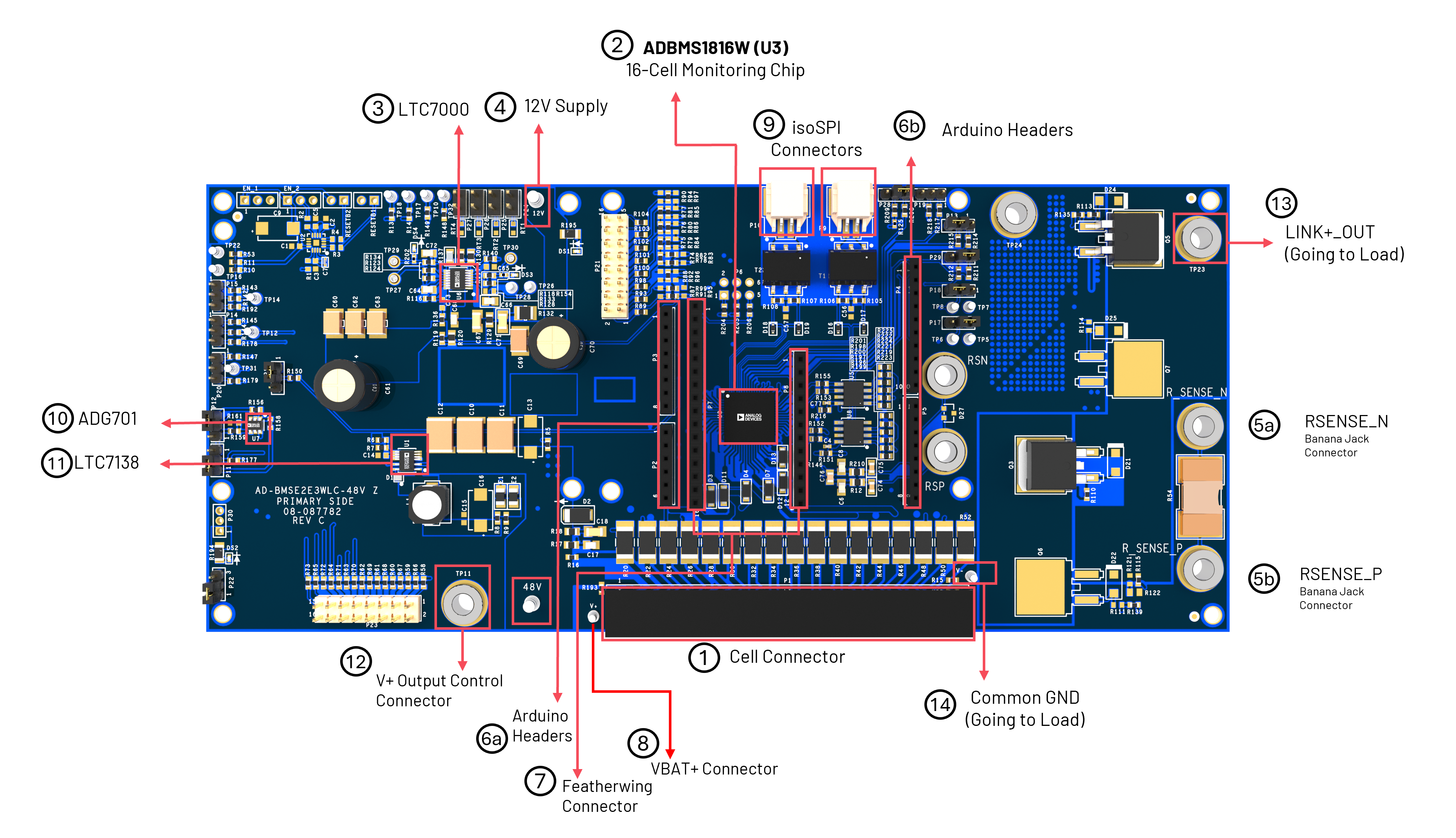
https://media.githubusercontent.com/media/analogdevicesinc/documentation/main/docs/solutions/reference-designs/ad-bmse2e3wlc-48v/hardware-guide/baseboard-main-components.png

Figure 1 AD-BMSE2E3WLC-48V Components

No.

Component

Function

1

Battery Cell Connector

Connector going to battery cells

2

ADBMS1816W

Battery cell monitoring IC

3

LTC7000

FET driver IC

4

12V Supply

12V supply access

5a

Rsense_N

Resistor sensing for detecting and monitoring total current on the baseboard negative side

5b

Rsense_P

Resistor sensing for detecting and monitoring total current on the baseboard positive side

6a

Arduino Headers

Arduino header connector left side

6b

Arduino Headers

Arduino header connector right side

7

FeatherWing Connector

Connector for placing FeatherWing form- factor boards (for MCU connection)

8

VBAT+ Connector

Positive Terminal Connector for total voltage capacity of the battery pack

9

isoSPi Connectors

DuraClik isoSPi connector terminals

10

ADG701

5V switch USB enabled

11

LTC7138

5V analog and 5V digital LDO regulator

12

V+ Output Control Connector

Output control connector from V+ going to Link+ Output

13

LINK+_OUT

Access going to load side

14

Common GND

Access ground going to load side

Hardware Setup

Requirements

Jumper Configuration

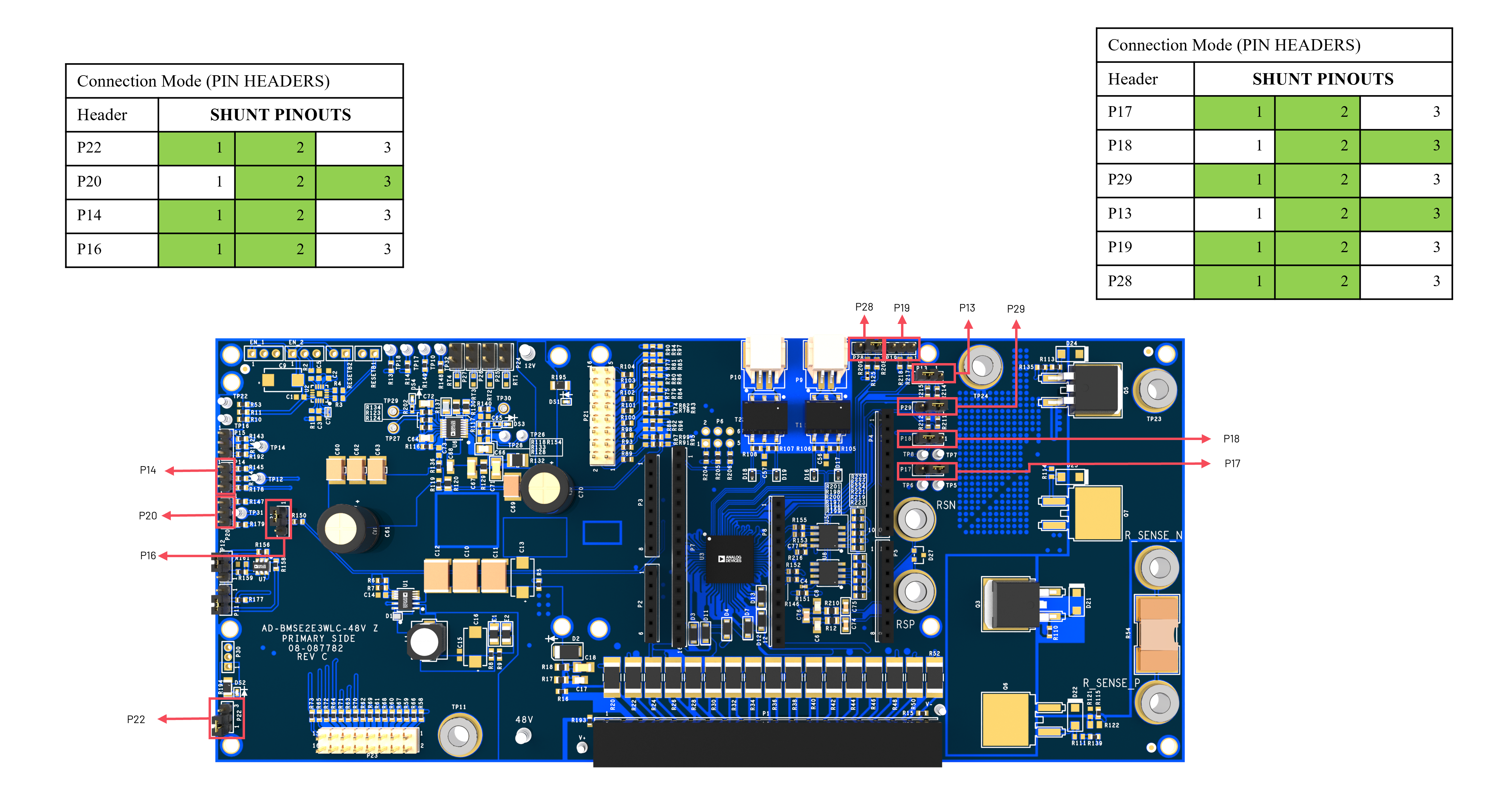
Install the shunt connectors (if not yet installed) and ensure correct positions, as highlighted in red in the figure below.

Important

Header P16 must be configured with the shunt installed between pin 2 and pin 3. This setting configures the board for 48V operation.

https://media.githubusercontent.com/media/analogdevicesinc/documentation/main/docs/solutions/reference-designs/ad-bmse2e3wlc-48v/hardware-guide/baseboard-shunt-config.png

Figure 2 AD-BMSE2E3WLC-48V Baseboard Shunt Configuration

Battery Emulator Setup

Note

The DC2472A Battery Emulator Board is used for cell voltage input in this setup.

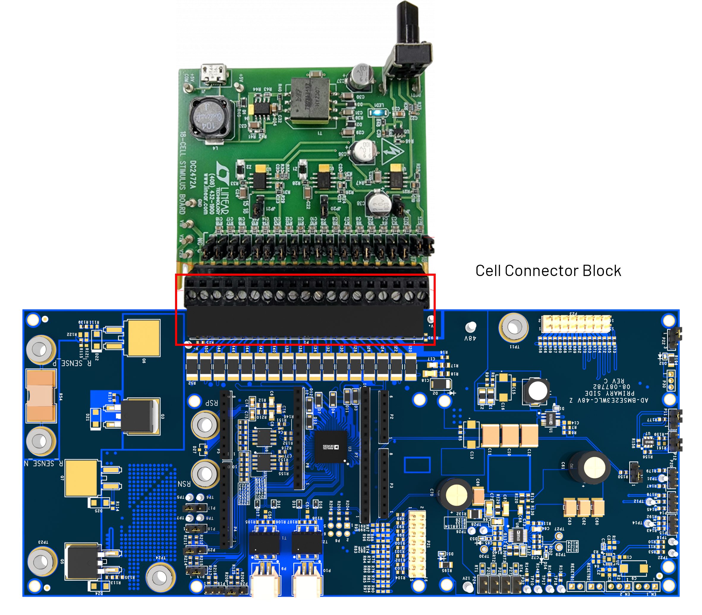
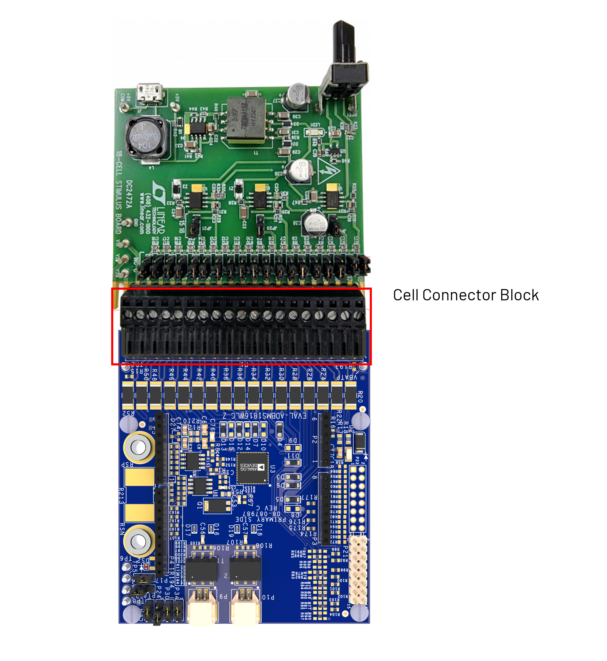
  • Plug the screw-terminal block into the cell voltage connector of the DC2472A battery emulator.

  • Connect the DC2472A battery emulator to the AD-BMSE2E3WLC-48V Baseboard through the cell connector.

    https://media.githubusercontent.com/media/analogdevicesinc/documentation/main/docs/solutions/reference-designs/ad-bmse2e3wlc-48v/hardware-guide/baseboard-to-emulator.png

    Figure 3 AD-BMSE2E3WLC-48V to Battery Emulator Setup

  • Connect a 5V external power source to the DC2472A battery emulator (J1) using a USB cable. External power supply is recommended for adequate power.

  • Alternatively, power it through a PC using a USB cable.


    Power Verification

    After powering up:

    • On DC2472A:

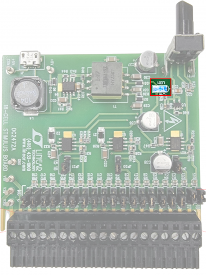
      • Blue LED (LED1) should turn ON

        https://media.githubusercontent.com/media/analogdevicesinc/documentation/main/docs/solutions/reference-designs/ad-bmse2e3wlc-48v/hardware-guide/emulator-led-on.png

        Figure 4 DC2472A Emulator Power LED

    • On AD-BMSE2E3WLC-48V Baseboard:

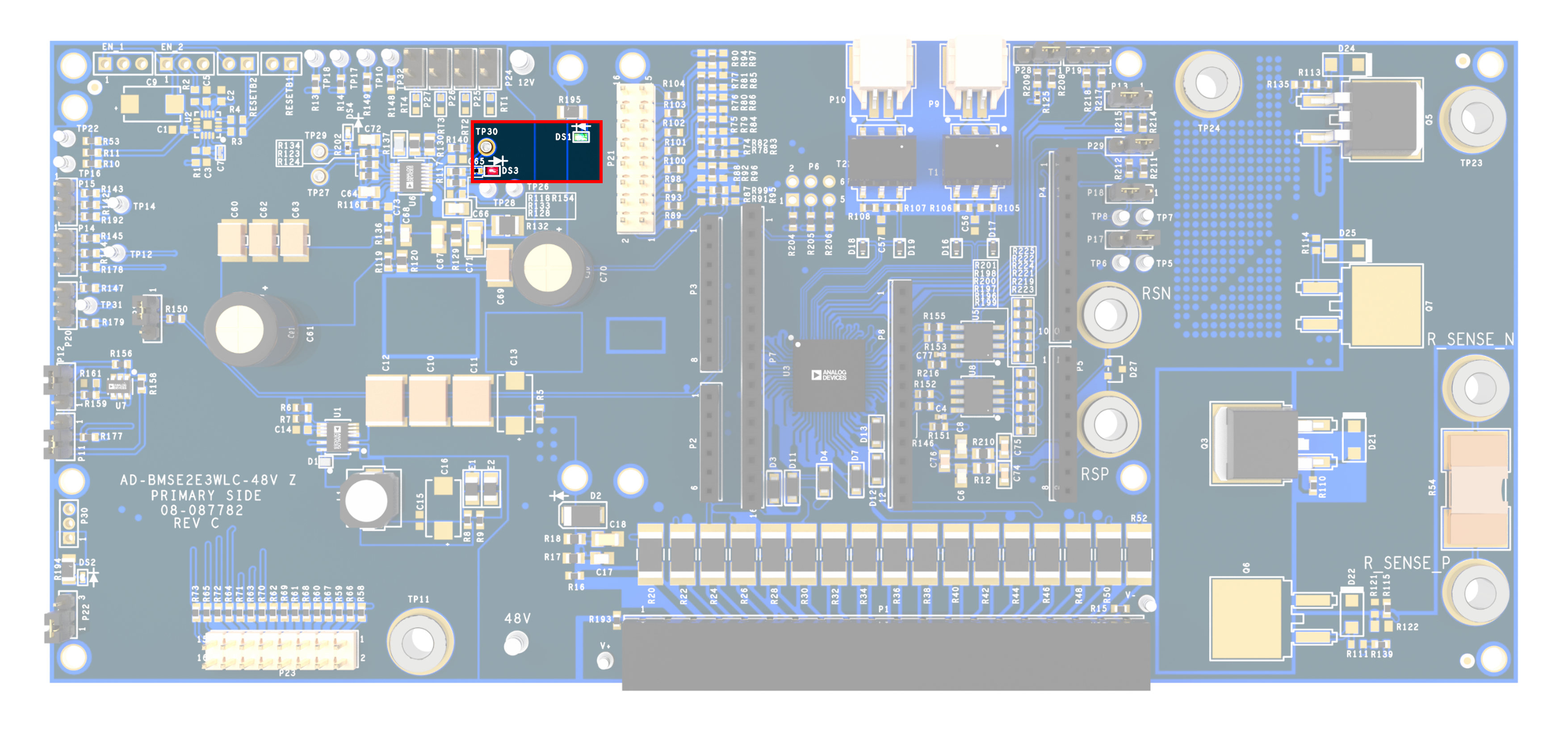
      • Red LED (DS3) and Green LED (DS1) should turn ON

        https://media.githubusercontent.com/media/analogdevicesinc/documentation/main/docs/solutions/reference-designs/ad-bmse2e3wlc-48v/hardware-guide/baseboard-led-on.png

        Figure 5 AD-BMSE2E3WLC-48V Baseboard Power LED

Cell Voltage Measurement Using DMM

Using a Digital Multimeter (DMM):

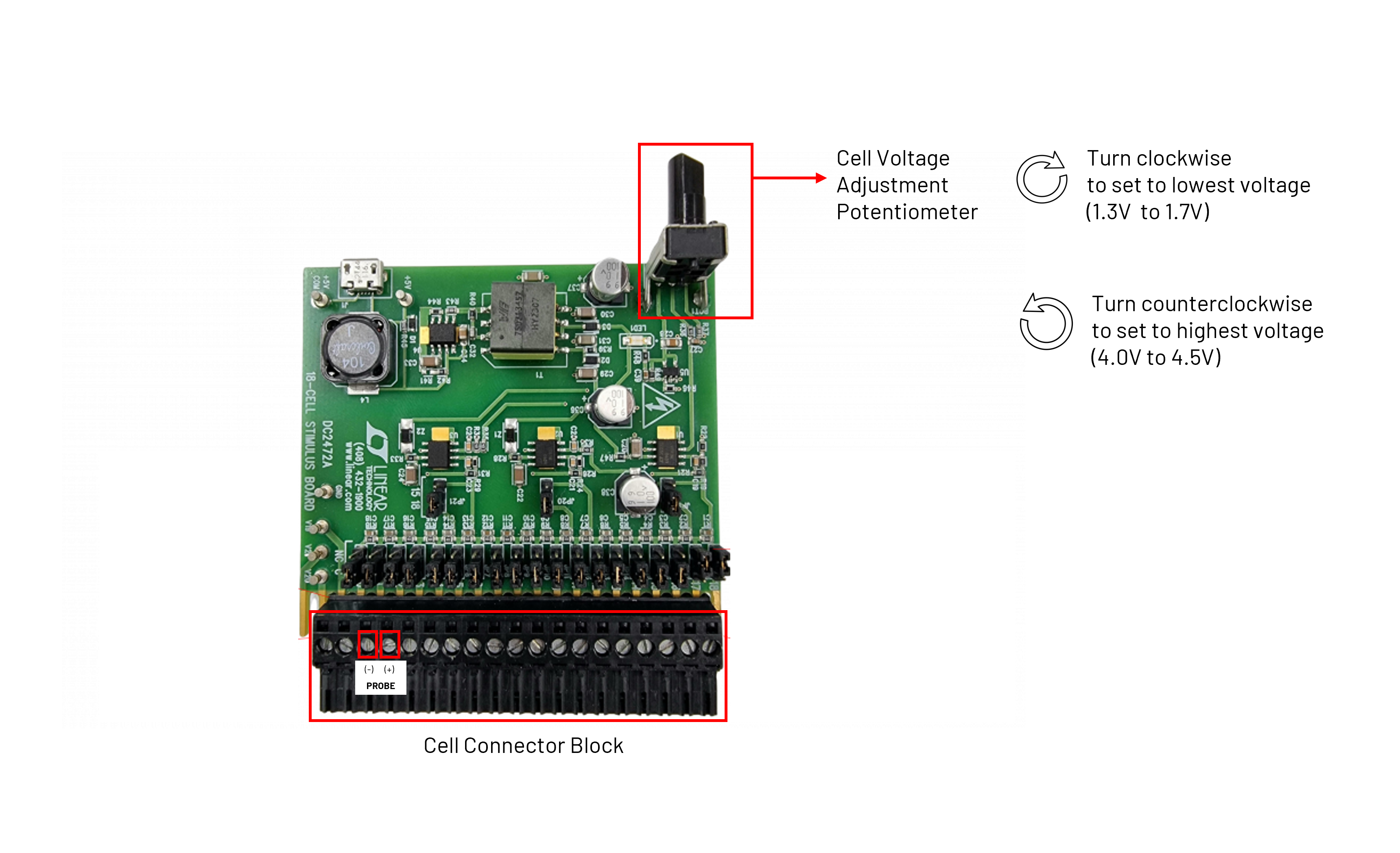
Rotate the knob of the DC2472A clockwise to set it to the lowest voltage. Record the measurement for each cell voltage (C1 to C16).

  • Set the DMM to voltage mode

  • Place the probes (+) and (–) between adjacent cells to measure voltage

  • The reading should fall within the specified range to be considered “good”; otherwise, mark it as “bad”

  • Do not remove the supply during measurement

  • Clockwise → lowest voltage (1.3V to 1.7V)

  • Counterclockwise → highest voltage (4.0V to 4.5V)

https://media.githubusercontent.com/media/analogdevicesinc/documentation/main/docs/solutions/reference-designs/ad-bmse2e3wlc-48v/hardware-guide/emulator-potentiometer.png

Figure 6 DC2472A Battery Emulator Potentiometer

Expected Reading between Cells for AD-BMSE2E3WLC-48V

RANGE (V)

C1

C2

C3

C4

C5

C6

C7

C8

C9

C10

C11

C12

C13

C14

C15

C16

ASSESSMENT

4.0 to 5.0

4

4

4

4

4

4

4

4

4

4

4

4

4

4

4

4

GOOD

1.3 to 1.7

1.431

1.431

1.431

1.431

1.431

1.431

1.431

1.431

1.431

1.431

1.431

1.431

1.43

1.43

1.43

1.43

GOOD

Test Point Measurement

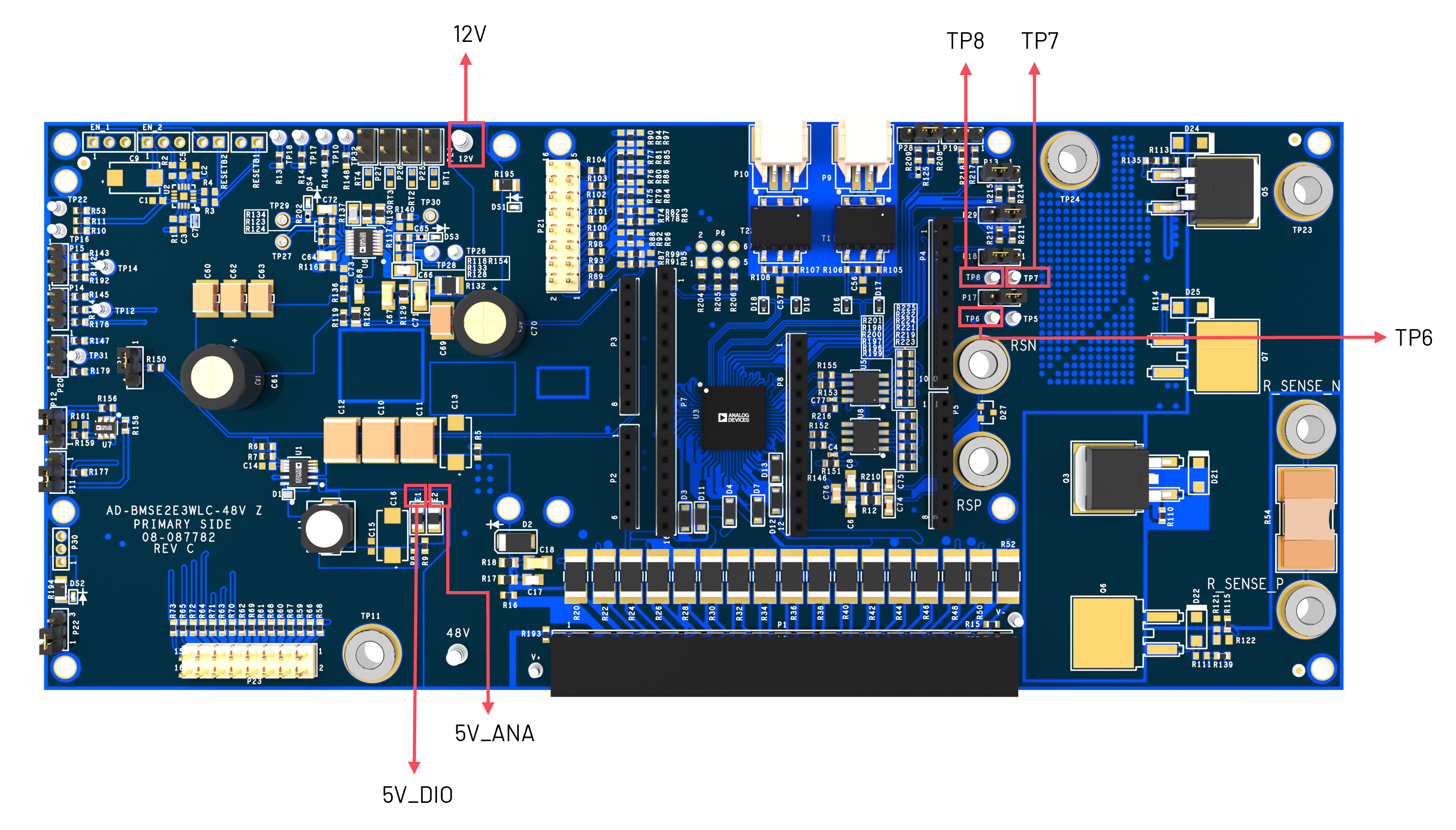
Using the DMM, measure the following test points (TP) and verify whether each reading is within range. Mark as “Good” if within range; otherwise, mark as “Bad”. Remove the USB supply after completing the test.

https://media.githubusercontent.com/media/analogdevicesinc/documentation/main/docs/solutions/reference-designs/ad-bmse2e3wlc-48v/hardware-guide/baseboard-test-points.png

Figure 7 AD-BMSE2E3WLC-48V Test Points

Expected Readings at Test Points

Test Point

Name

Typical (V)

Range (V)

Assessment/Result

TP6

PORT

4.9

4.5 to 5.15

Good

TP8

TRANS

0

0

Good

TP7

VREG

4.9

4.7 to 5.15

Good

12V

12V SUPPLY

11.9

11.5 to 12.5

Good

E1 (PIN2)

5V_ANA

5

4.5 to 5.15

Good

E2 (PIN2)

5V_DIG

5

4.5 to 5.15

Good


Full System Integration Setup

Requirements

  • 1 × AD-BMSE2E3WLC-48V Baseboard

  • 1 × EVAL-ADBMS1816WLC Daughter Board

  • 2 × DC2472A Battery Emulator

  • 1 × MAX32666FTHR Microcontroller

  • 1 × MAX32625PICO Programming Board

  • 2 × isoSPi twisted-pair cables

  • 1 × 10-pin swd debugger cable

  • 3 × Micro-USB to USB cables

  • 1 × PC/Laptop

  • 2 × Red Alligator-to-Banana Plug Cables (1166-12-0)

  • 2 × Black Alligator-to-Banana Plug Cables (1166-12-0)

  • 12 × Pin Header Shunts (if not yet installed)

  • 1 × Digital Multimeter (DMM)

EVAL-ADBMS1816WLC Daughter Board Setup

From the list of required hardware, select the EVAL-ADBMS1816WLC Daughter Board.

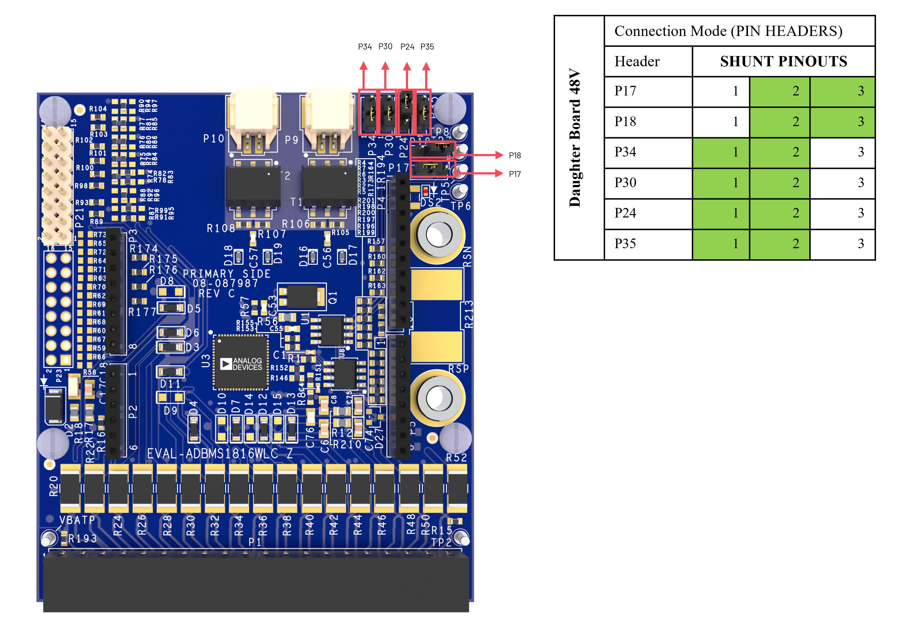
  • Configure the shunt connectors in P17, P24, P34, P30, P18, and P35. Refer to the pin positions in the figure below for proper shunt configuration.

    https://media.githubusercontent.com/media/analogdevicesinc/documentation/main/docs/solutions/reference-designs/ad-bmse2e3wlc-48v/hardware-guide/daughterboard-shunt-configuration.png

    Figure 8 EVAL-ADBMSE2E3WLC Daughter Board Shunt Configuration

  • Connect the second DC2472A battery emulator to the EVAL-ADBMS1816WLC Daughter Board through the cell connector.

    https://media.githubusercontent.com/media/analogdevicesinc/documentation/main/docs/solutions/reference-designs/ad-bmse2e3wlc-48v/hardware-guide/daughterboard-to-emulator.png

    Figure 9 EVAL-ADBMS1816WLC to Battery Emulator Setup

Microcontroller Connection

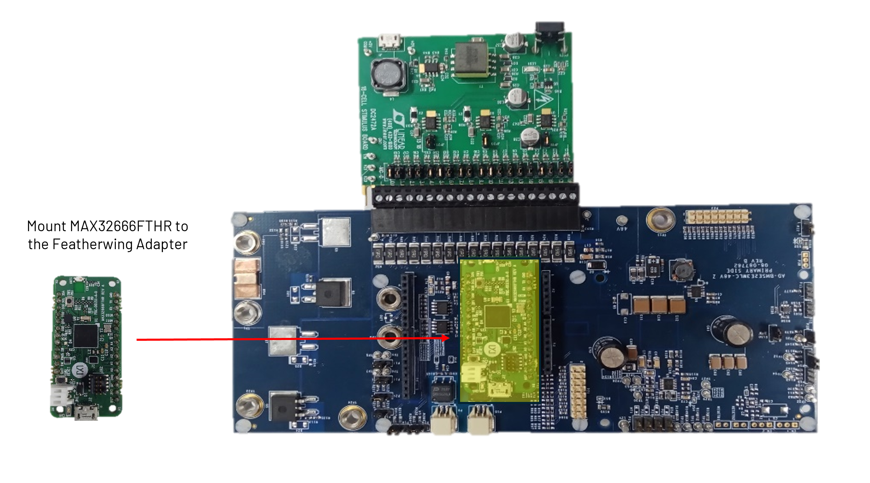
  • Attach the MAX32666FTHR microcontroller to the AD-BMSE2E3WLC-48V Baseboard through the Featherwing connector.

    https://media.githubusercontent.com/media/analogdevicesinc/documentation/main/docs/solutions/reference-designs/ad-bmse2e3wlc-48v/hardware-guide/baseboard-to-max32666fthr.png

    Figure 10 MAX32666FTHR Mounted to the AD-BMSE2E3WLC-48V Baseboard

48V Connection

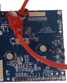
  • Connect the red alligator to banana jack cable between 48V and TP11 on the AD-BMSE2E3WLC-48V as shown below.

    https://media.githubusercontent.com/media/analogdevicesinc/documentation/main/docs/solutions/reference-designs/ad-bmse2e3wlc-48v/hardware-guide/48v-connection.png

    Figure 11 48V Connection

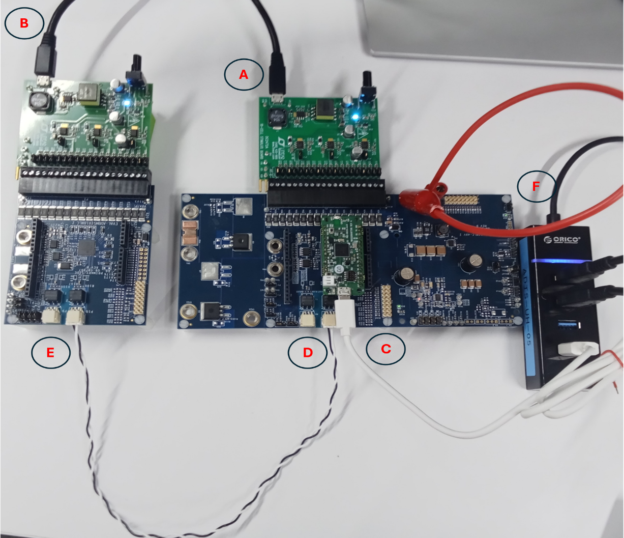
Cable and PC Connection

(A). Plug the micro-USB cable to the first DC2472A battery emulator that is connected to AD-BMSE2E3WLC-48V.

(B). Plug the micro-USB cable to the second DC2472A battery emulator that is connected to EVAL-ADBMS1816WLC.

(C). Plug the micro-USB cable into the MAX32666FTHR.

(D). Connect the 2-wire isoSPi cable on P10 of AD-BMSE2E3WLC-48V.

(E). Connect the other end of the 2-wire isoSPi cable to P10 of EVAL-ADBMS1816WLC.

(F). Connect all USB cables to a USB hub (preferred).

Note

If your PC/laptop USB ports can supply ≥1 A, you may connect devices directly without a USB hub.

Your setup should look like below:

https://media.githubusercontent.com/media/analogdevicesinc/documentation/main/docs/solutions/reference-designs/ad-bmse2e3wlc-48v/hardware-guide/full-integration-setup.png

Figure 12 Full Hardware Evaluation Setup


Sample Application Setup

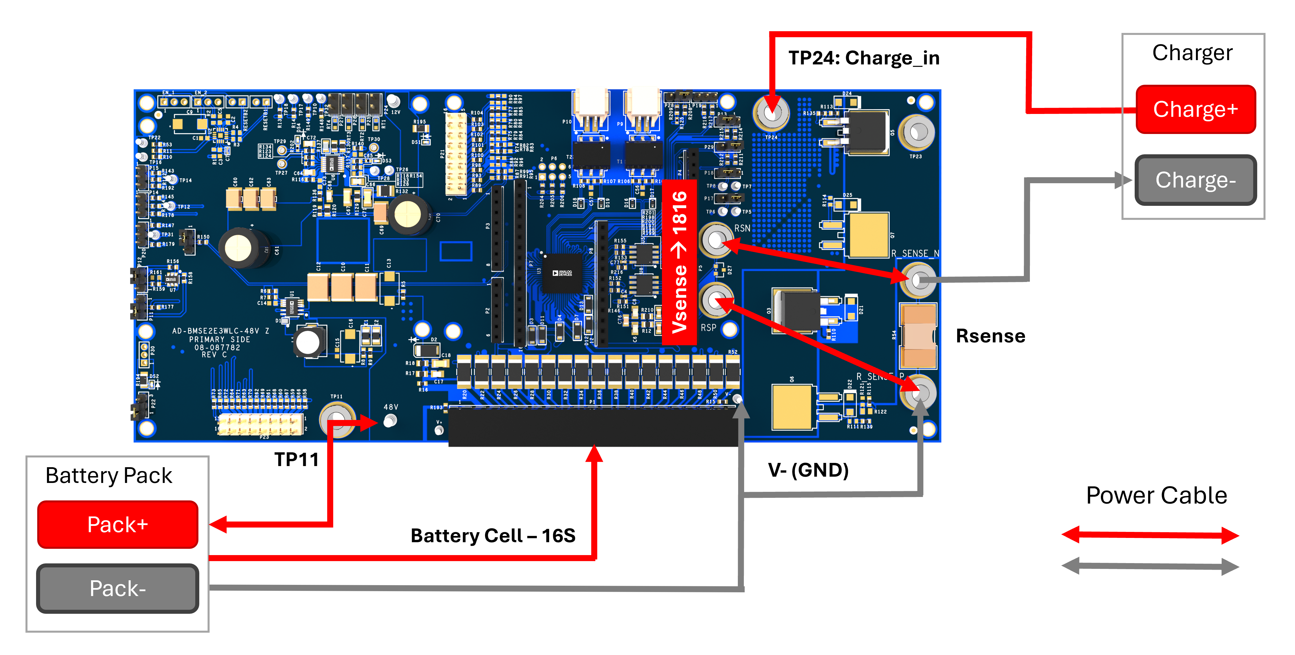
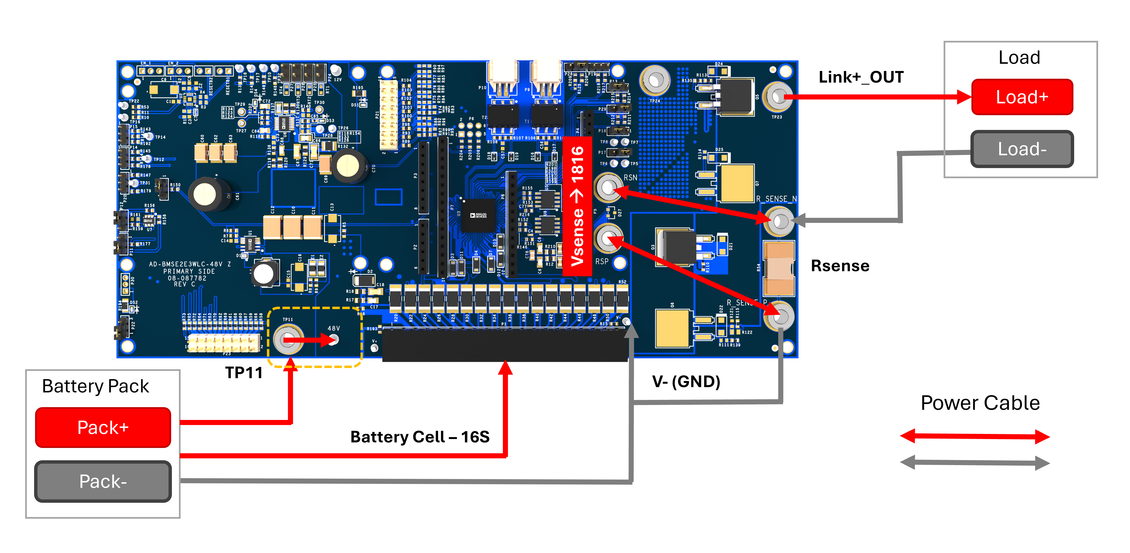
Refer to the diagram below for the sample application setup for Charge and Discharge applications.

Charge Application

https://media.githubusercontent.com/media/analogdevicesinc/documentation/main/docs/solutions/reference-designs/ad-bmse2e3wlc-48v/hardware-guide/charge-application.png

Figure 13 Charge Application Setup

Discharge Application

https://media.githubusercontent.com/media/analogdevicesinc/documentation/main/docs/solutions/reference-designs/ad-bmse2e3wlc-48v/hardware-guide/discharge-application.png

Figure 14 Discharge Application Setup

Tip

The AD-BMSE2E3WLC-48V can be evaluated through the ACE GUI by running the AD-BMSE2E3WLC-SL software package. Access the software resources and see the setup procedure in the Software User Guide.