AD4130-8 IIO Application
Introduction
This page gives an overview of using the ARM platforms supported (default is Mbed) firmware example with the Analog Devices EVAL-AD4130-8WARDZ evaluation board and SDP-K1 controller board. This example code leverages the ADI developed IIO (Industrial Input Output) ecosystem to evaluate the AD4130-8 device by providing device debug and data capture support.
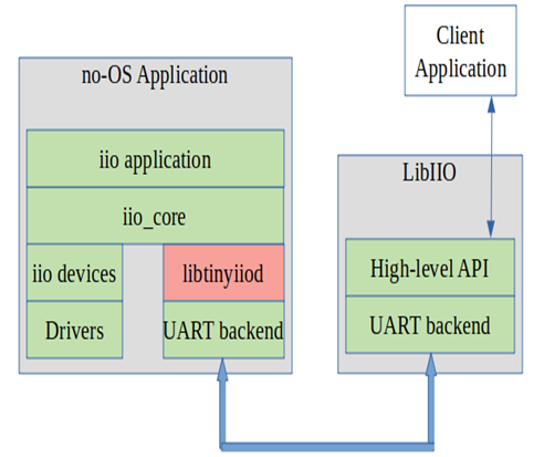
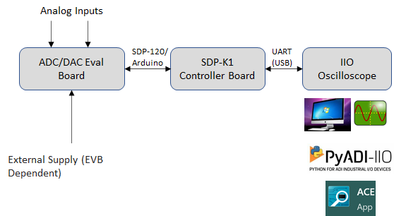
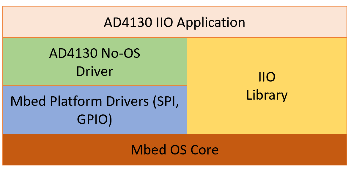
IIO Oscilloscope is used as a client application running on Windows, which is an ADI-developed GUI for ADC data visualization and device debug. The interface used for communicating the client application with the firmware application (IIO device) is UART. The firmware application communicates with the IIO device using ADI No-OS drivers and platform drivers low level software layers. SDP-K1 is used as the controller board, on which the IIO firmware application runs.
Note
SDP-K1 can also support high speed VirtualCOM port at 1 Mbps or higher for faster data transmission.
This code has been developed and tested on the SDP-K1 Controller Board using the on-board SDP-120 Headers. However, the same code can be used without or with little modification on any Mbed enabled board which has Arduino Header support, such as STM32-Discovery, STM32-Nucleo, etc.
Useful links
Hardware Connections
Jumper Settings
SDP-K1: Connect the VIO_ADJUST jumper on the SDP-K1 board to the 3.3 V position to drive SDP-K1 GPIOs at 3.3 V.
EVAL-AD4130-8WARDZ:
Stack the EVAL-AD4130-8WARDZ on the Arduino connectors of the SDP-K1 board.
Set the evaluation board link options for the sensor demo mode you intend to run (see the Hardware Link Options section of the hardware guide).
UART Connections
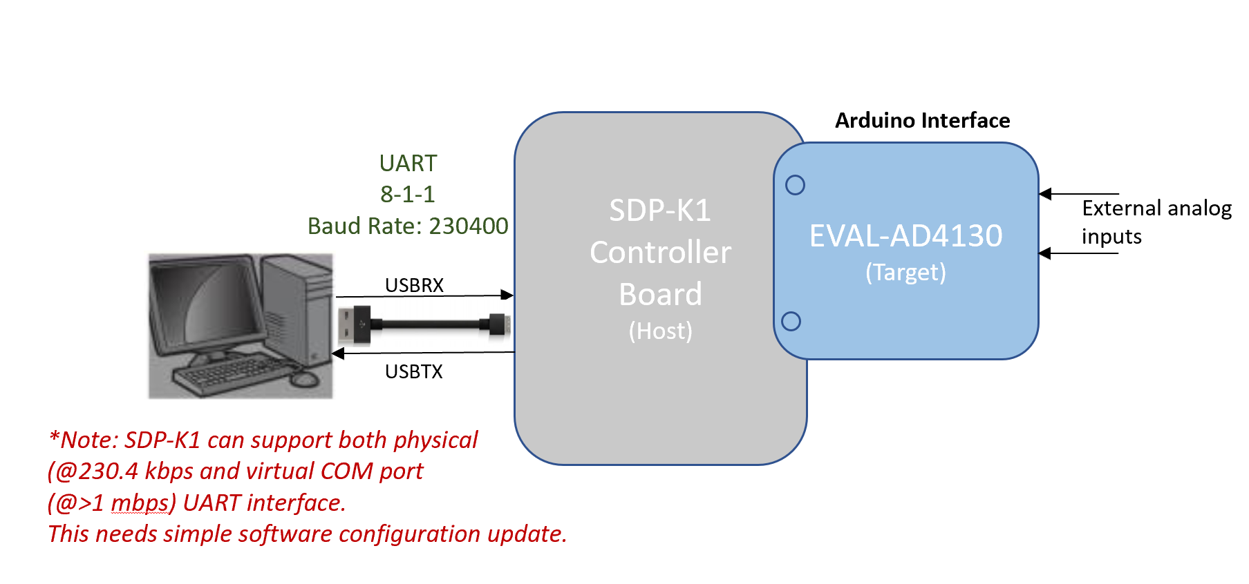
For data transmission to the IIO client, VirtualCOM or UART serial communication is used. SDP-K1 by default uses the VCOM serial interface for higher speed data transmission.
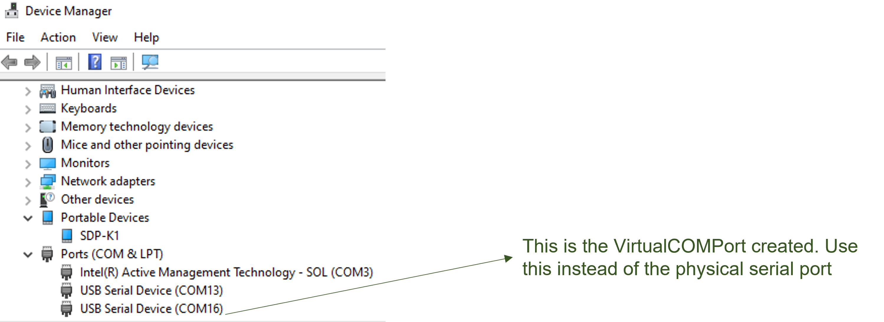
SDP-K1 is powered through USB connections from the computer. SDP-K1 acts as a serial device when connected to a PC, which creates a COM port to connect to IIO Oscilloscope GUI running on Windows. The COM port assigned to a device can be seen through the Device Manager.
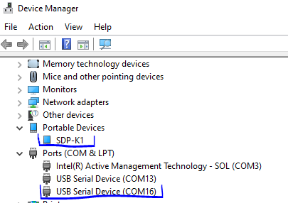
SDP-K1 can support high speed VirtualCOM port USB interface, so by
default VCOM is configured as the default interface in the firmware. The
interface can be set to UART by defining the macro USE_PHY_COM_PORT
in the app_config.h file.

Note
The actual COM port number for your device may not be the same as shown above. Always check your SDP-K1 serial COM port number before connecting to the IIO client.
Software Downloads
MBED Firmware
Source code is hosted in the precision-converters-firmware repository.
Build guide: Precision Converters MBED Firmware
Libiio: IIO Library
This library provides an abstracted interface to communicate between the IIO device and the IIO client application (IIO Oscilloscope) without worrying about the low level hardware details.
IIO Oscilloscope (Client)
This is a GUI-based IIO client application for data visualization and device configuration/debugging. The data from IIO devices (ADCs/DACs) is transmitted over Serial/Ethernet/USB link to IIO Oscilloscope through the abstracted layer of libiio.
Evaluating AD4130-8 Using IIO Ecosystem
Ensure that the hardware connection has been made properly between the Controller Board (SDP-K1) and the ADC Eval board. Also ensure all software (IIO firmware, libiio, and IIO Oscilloscope) is downloaded and installed on your computer before trying to communicate with the device.
Running IIO Oscilloscope (Client)
Open the IIO Oscilloscope application from the start menu and configure the serial (UART) settings as shown below. Click the refresh button and the AD4130-8 device should appear in the IIO devices list.
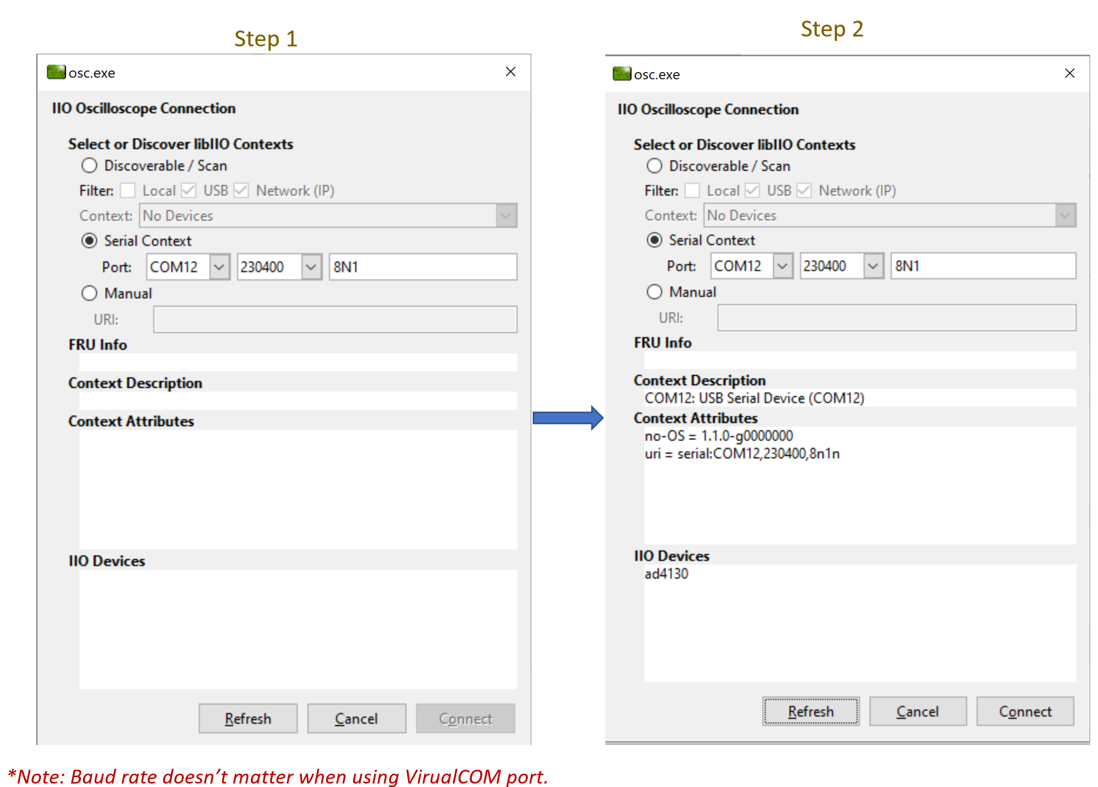
Click “Connect” and it should by default open the data “Capture” window. You can drag aside or close this window to see the main “Debug and DMM” tab window.
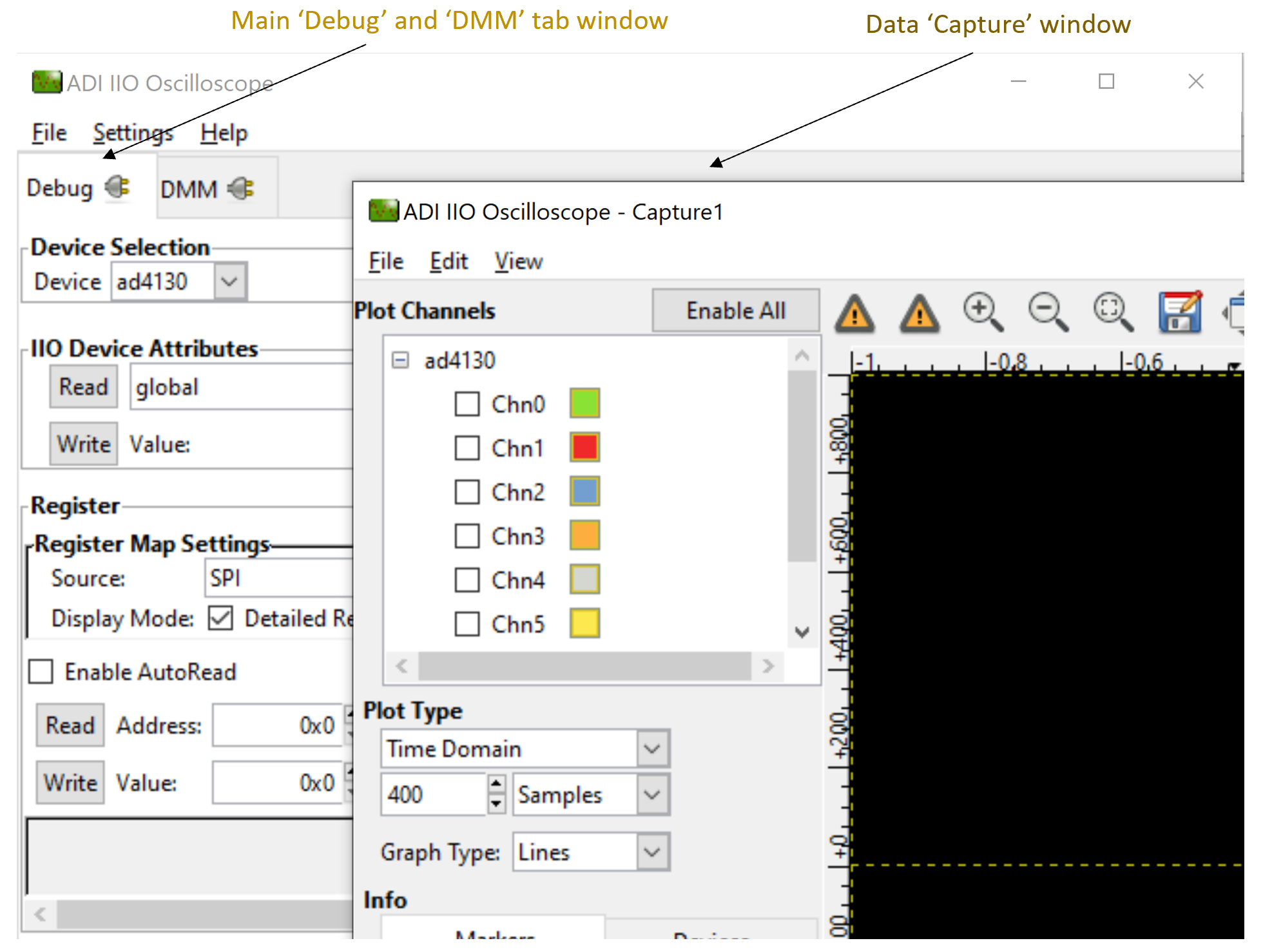
Configure/Access Device Attributes (Parameters)
The IIO Oscilloscope allows the user to access and configure different device parameters, called “Device Attributes”. There are 2 types of attributes:
Device Attributes (Global): Access/Configure common device parameters.
Channel Attributes (Specific to channels): Access/Configure channel specific device parameters.
How to read and write an attribute:
To read an attribute, simply select the attribute from the list or press the “Read” button on the left side.
To write an attribute, select the attribute value in the “value field” and press the “Write” button.
Using DMM Tab to Read DC Voltage on Input Channels
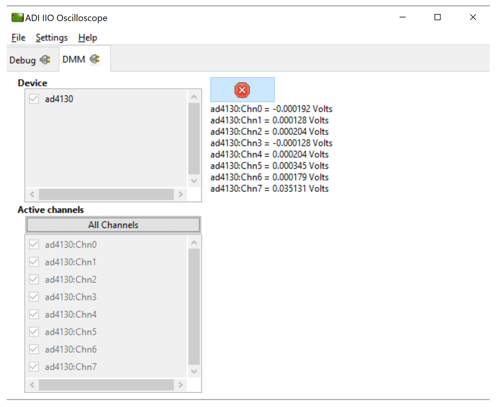
The DMM tab can be used to read the instantaneous voltage applied on analog input channels. Simply select the device and channels to read and press the start button.
Note
The voltage is just instantaneous, so it is not possible to get RMS AC voltage or averaged DC voltage. Also, when using the DMM tab, do not access/use the Data Capture or Debug tab as this could impact data capturing. Both DMM scan and data capture use different methods of conversion. The DMM data is read using single conversion, while data capture uses continuous conversion mode of operation.
Data Capture from IIO Device
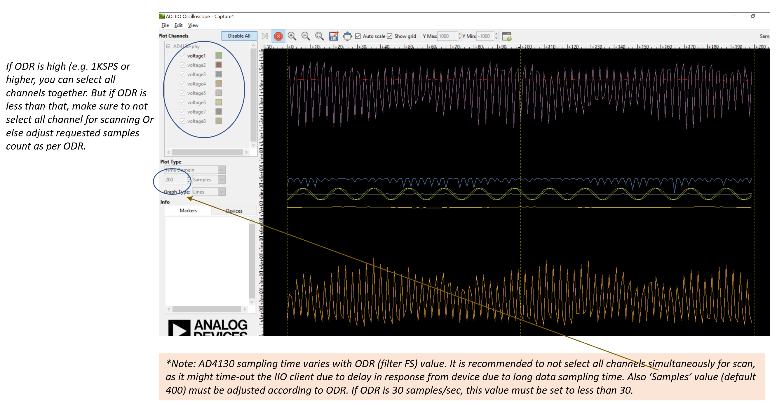
To capture data from the AD4130-8 IIO device, simply select the device and channels to read/capture data. The data is plotted as “ADC Raw Value” vs “Number of Samples” and is used for visualization. The data is read as-is from the device without any processing. If the user wants to process the data, it must be done externally by capturing data from the serial link on the controller board.
Note
The DMM or Debug tab should not be accessed when capturing data as this would impact data capturing. Both DMM scan and data capture use different methods of conversion. The DMM data is read using single conversion, while data capture uses continuous conversion mode of operation.
Time Domain Plot
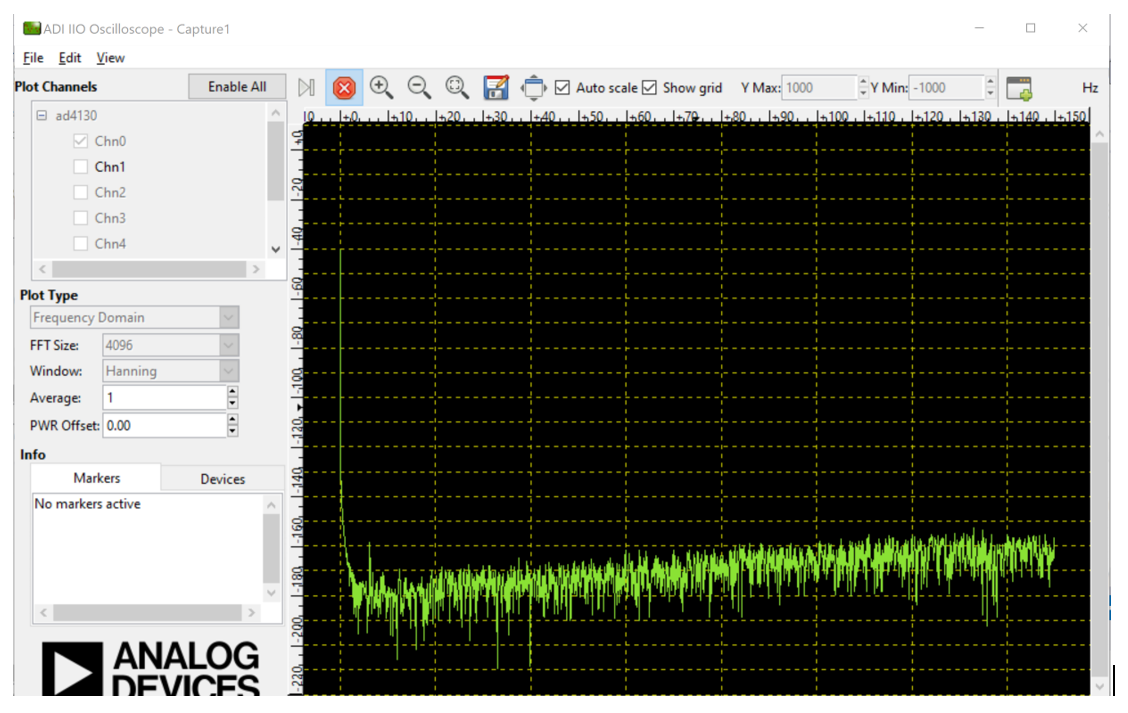
Frequency Domain Plot
Note
Max 4096 samples can be selected for plotting frequency domain response due to limited buffer size in the firmware.
Sensor Demo Modes
The AD4130-8 firmware supports a set of sensor demo modes that configure the device and evaluation board for a specific measurement application, such as RTD, thermocouple, thermistor, load cell, ECG and noise measurement.
Demo Mode Selection
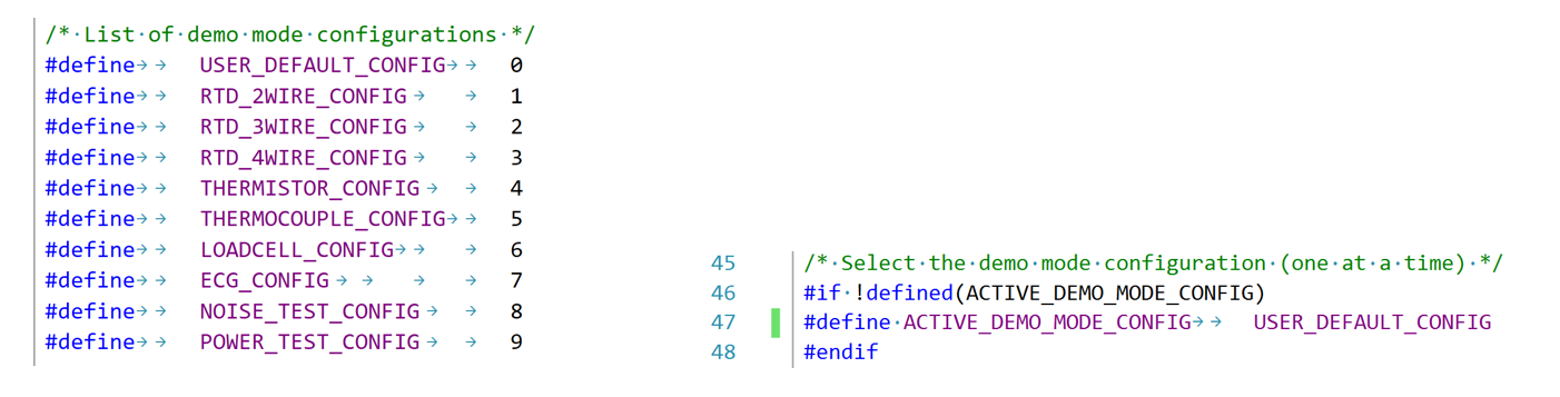
The active sensor demo mode is selected at compile time using the
ACTIVE_DEMO_MODE_CONFIG macro in the app_config.h file. Rebuild
and reprogram the firmware after changing the selected demo mode.
Demo Mode User Configuration
Each demo mode has an associated user configuration that sets the channels, setups, filter, output data rate, excitation and reference options appropriate for the selected sensor. Set the evaluation board link options to match the selected demo mode.

Sensor Measurement
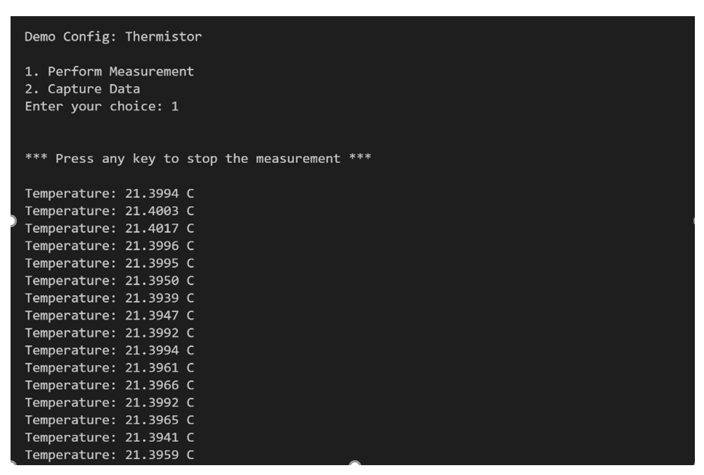
Once the firmware is running in the selected demo mode, connect the sensor to the corresponding connector and capture data through the IIO Oscilloscope or the Python scripts. The measured value (for example, temperature in degrees Celsius) is printed on the console for the demo modes that perform a sensor-to-engineering-units conversion.
Sensor Channels Calibration
The firmware supports internal and system calibration of the ADC channels. Calibration is performed at initialization for the active setups; the calibration coefficients (offset and gain) are then applied to subsequent conversions to improve measurement accuracy.
Python Environment and Scripts
Data capture, device calibration, etc. can be achieved with Python-based IIO clients, using the pyadi-iio library. A possible option using ADI’s pyadi-iio library in Python has been demonstrated in the following sections. The Python scripts are provided along with the firmware package.
Setting-up Python Environment
Install Python on your local machine. The scripts are developed and tested using Python 3.9.0; version 3.9.0 or newer is recommended.
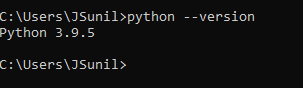
Once Python is installed, make sure the environment path (on Windows) is set properly. Verify by running
python --versionon a command line tool such as Git Bash, Command Prompt, or PowerShell.
Install the pyadi-iio package by running
python -m pip install pyadi-iio.

Modifying/Running Python Scripts
All Python scripts specific to the AD4130-8 IIO firmware are stored in the
scriptsfolder in the project directory.Update the
uriinterface in the script according to the COM port assigned to your device (SDP-K1). Default COM port is set to COM16 in all scripts.Update the
device_namevariable to match the device name in the compiled firmware (ad4130).

Output Obtained from the Python Script
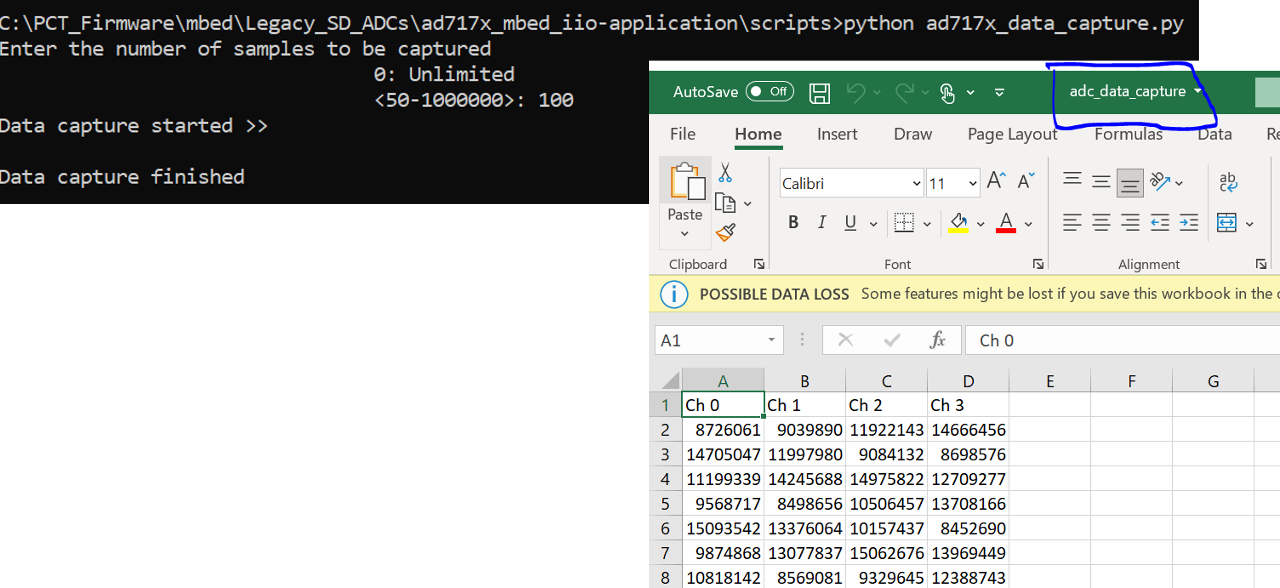
On execution, the script requests the number of samples to be entered by
the user. This should be a multiple of the defined sample block size. On
successful completion of capturing n samples, the data is displayed on
the screen and the data points are stored in a CSV file as
adc_data_capture.csv in the folder where the script is located.

AD4130-8 Firmware Structure
app_config.h
This file can be used to:
Select the active platform using the macro
ACTIVE_PLATFORM_MBED(only Mbed is supported).Select the physical (UART) or virtual (VCOM) serial interface using the
USE_PHY_COM_PORTmacro. VCOM is used by default.Select the active sensor demo mode using the
ACTIVE_DEMO_MODE_CONFIGmacro.Enable FIFO based data capture using the
FIFO_ENABLEDmacro.
ad4130_user_config.c
This file defines the user configurations for the AD4130-8, such as SPI parameters (frequency, mode, etc.) and other init parameters used by No-OS drivers to initialize the AD4130-8 device (gain, data output rate, reference voltage, etc.).
ad4130_data_capture.c
This file implements the data capturing logic for the AD4130-8 device. The data capturing can be done using the normal sequencer mode or the FIFO mode.
ad4130_iio.c
This file defines getter/setter functions for all the device and channel specific attributes (related to the AD4130-8 device) to read/write the device parameters. The majority of device specific functionality is present in this module.
No-OS Drivers for AD4130-8
The No-OS drivers provide the high level abstracted layer for the digital interface of the AD4130-8 device. The complete digital interface (to access the memory map and perform data read) is done in integration with platform drivers. The functionality related to No-OS drivers is covered in the following files:
ad413x.cad413x.h