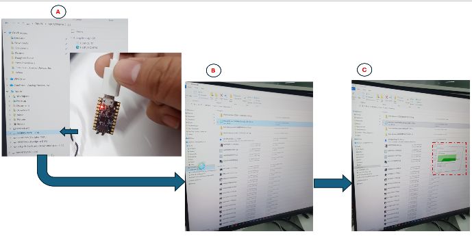
Connect the 10-pin SWD ribbon cable to the MAX32666FTHR.
Connect the other end to the MAX32625PICO.
Connect the MAX32625PICO to your PC using a micro-USB cable.
Download the MAX32625PICO image (see link above).
Extract the contents of the archive and locate the MAX32625_PICO.bin file.
Copy the MAX32625_PICO.bin file into the MAINTENANCE folder of the connected MAX32625PICO.
Wait for the transfer to complete.
Figure 1 Uploading the MAX32625_PICO.bin file
Successful installation indicators:
The device renames to DAPLINK.
A MAX32666.HTM file appears in the folder.
Pre-built Binaries
Pre-built .hex files are provided in the bin/ folder for supported
boards. No additional toolchain or build setup is required. Copy the
appropriate file onto the MAX32625PICO DAPLINK debugger drive.
The number of active devices is determined at runtime by the VSEL jumper:
LOW = 1 device / 48V
HIGH = 2 devices / 96V
If a different example or configuration is required, build the firmware
binaries from source.
Flash the Pre-built Binary File into the MAX32666FTHR
Download the AD-BMSE2E3WLC-SLFirmware1.0.0 package.
Copy the matching .hex file (select based on the MCU board used) from the bin/ folder to the DAPLINK drive.
The MAX32625PICO debugger flashes the MCU and remounts the drive when complete.
Verification:
A successful upload is indicated by the absence of a FAIL.TXT file
in the DAPLINK folder.
Command Line Interface
The AD-BMSE2E3WLC-SL firmware allows device monitoring and diagnostics through a command-line interface (CLI).
For this purpose, a terminal emulator such as Tera Term is recommended.
Open the Tera Term application (other terminals can also be used, but Tera Term is recommended).
Select Serial, then choose the correct COM port number associated with the microcontroller.
Click the Setup tab, then SerialPort.
Set the speed to 115200.
Then, click the Newsetting button.
Click the Setup tab, then Terminal.
Under the New-line setting, set Receive to AUTO.
Click the hardware RESET button on the microcontroller board.
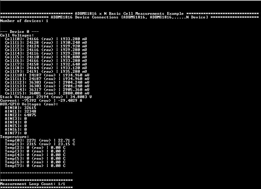
The BMS data will be printed on the Tera Term terminal.
Sample reading:
Figure 2 Sample BMS Data Output
Building the Firmware from Source
Since the AD-BMSE2E3WLC-48V baseboard is MCU-agnostic, users can swap the MAX32666FTHR MCU with any supported Maxim MCU.
The firmware can be built from scratch by following the instructions below:
Requirements
Extract the contents of the downloaded AD-BMSE2E3WLC-SLFirmware1.0.0 zip file. The package already includes no-OS and all
required sources. No git cloning or submodule initialization is required.
Select the desired example by editing the Makefile:
# Select the example measurement (Note: Select 1 example at a time)ADBMS1816_BASIC=n
ADBMS1816_BALANCING=n
ADBMS1816_DCC_BALANCING=n
ADBMS1816_FUEL_GAUGE=n
IIO_EXAMPLE=y
Note
Only one example should be set to y at a time.
Board Auto-Detection
Supported TARGET suffixes:
max32665fthr - MAX32665/MAX32666FTHR
max32690apard - APARD32690
max32690fthr - MAX32690FTHR
max32690 - defaults to APARD32690
Note
The Maxim toolchain uses max32665 for both MAX32665 and MAX32666.
Use max32665fthr when building for MAX32666FTHR.
# Total Number of ADBMS devices in the chainNUM_DEV=2# Delay in millisecondsMEASUREMENTS_FREQ_MS=1000# Set to 0 for continuous measurementsNUM_MEAS_LOOP=1# Set to y when measuring execution timeTIME_PROFILING?=n
# Use a separate serial portNO_OS_USB_UART=y
Note
NUM_DEV is a compile-time setting. The actual number of active devices
is determined at runtime by the VSEL jumper.
Jumper LOW -> 48V stack / 1 device
Jumper HIGH -> 96V stack / 2 devices
Ensure that the jumper position matches the hardware configuration.
Download the plugin package: Board.ADBMSE2E3WLC ACEZIP.zip (save locally)
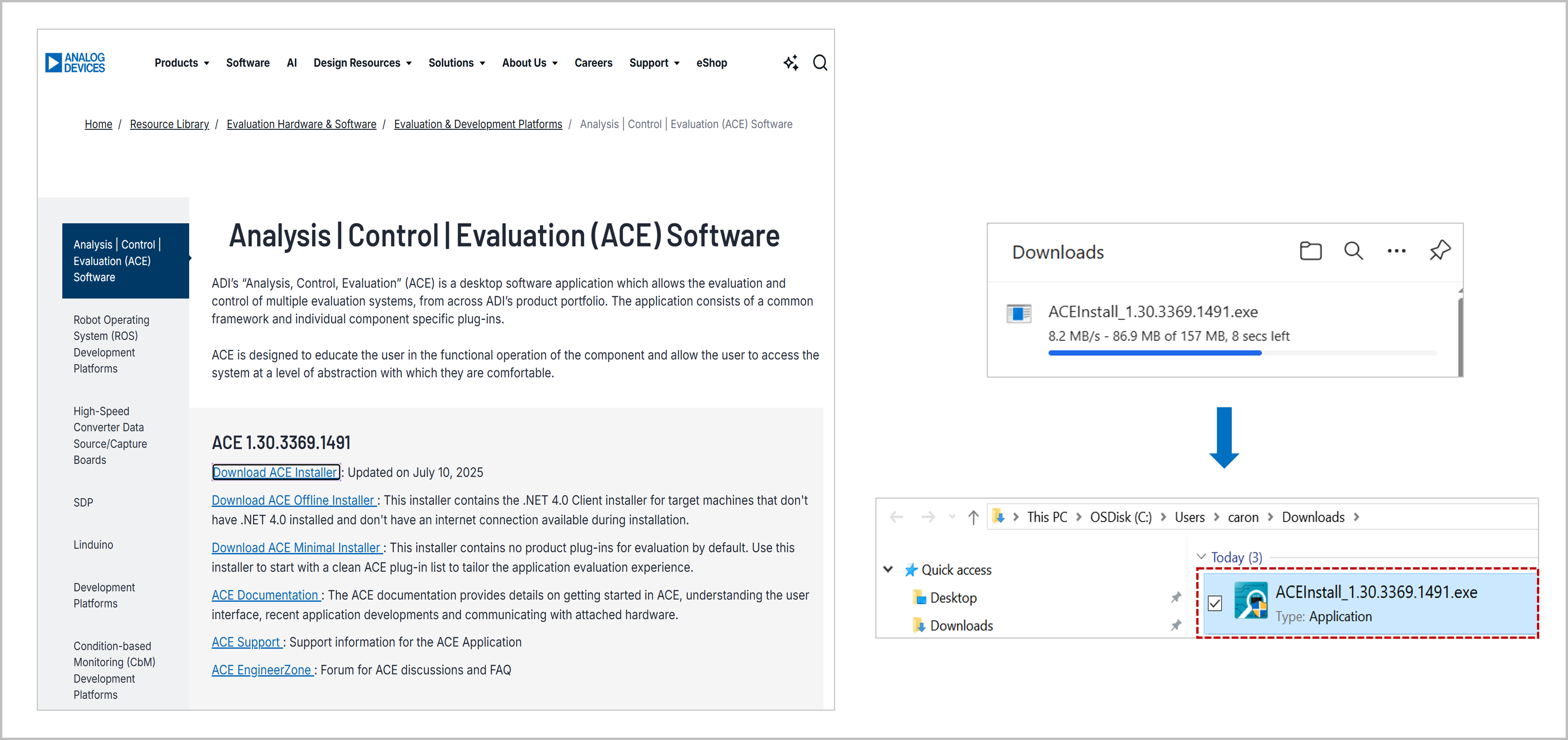
Download the latest ACE software from Analog Devices.
Figure 3 ACE Software Download
Step 2: Install ACE Software
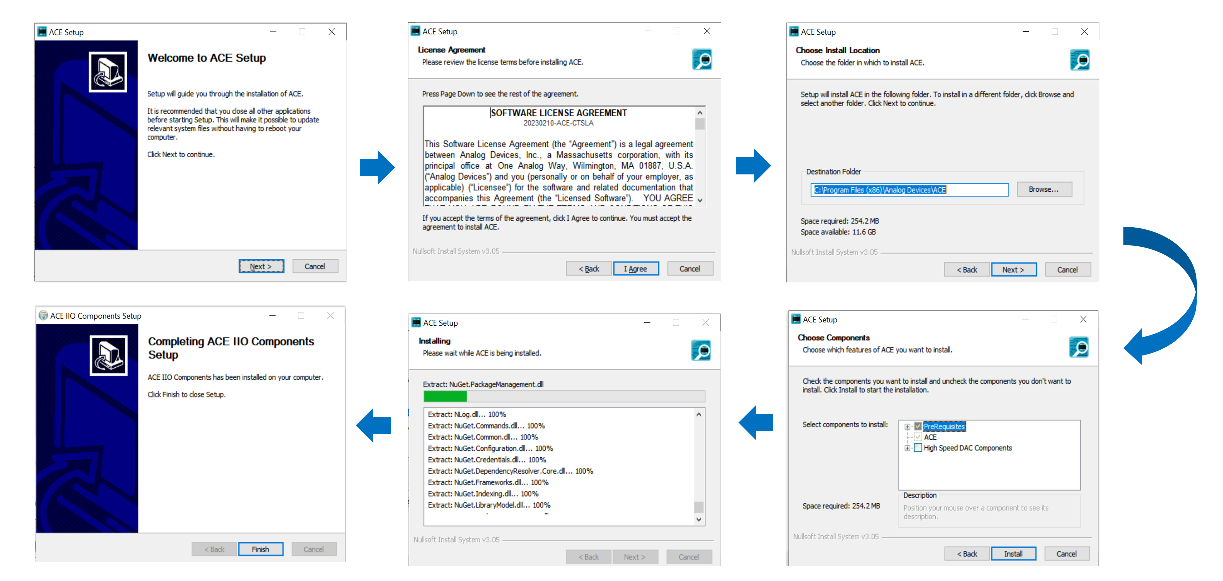
Run the installer.
Follow the on-screen installation steps shown in the following figures:
Figure 4 ACE Software Installation Steps
Verify the installation via the Start Menu.
Figure 5 ACE Software Start Menu Verification
Step 3: Load Plugin
Run the downloaded ACEZIP file.
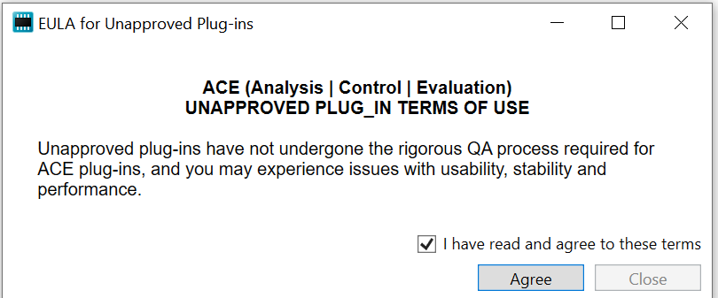
Accept the prompt warning about the unapproved EULA plugin.
Continue to load the plugin.
Figure 6 BMSE2E3WLC-SL Plugin
Launching and Configuring the GUI
Power up the hardware setup again (connect all USB cables to the PC or to a USB hub).
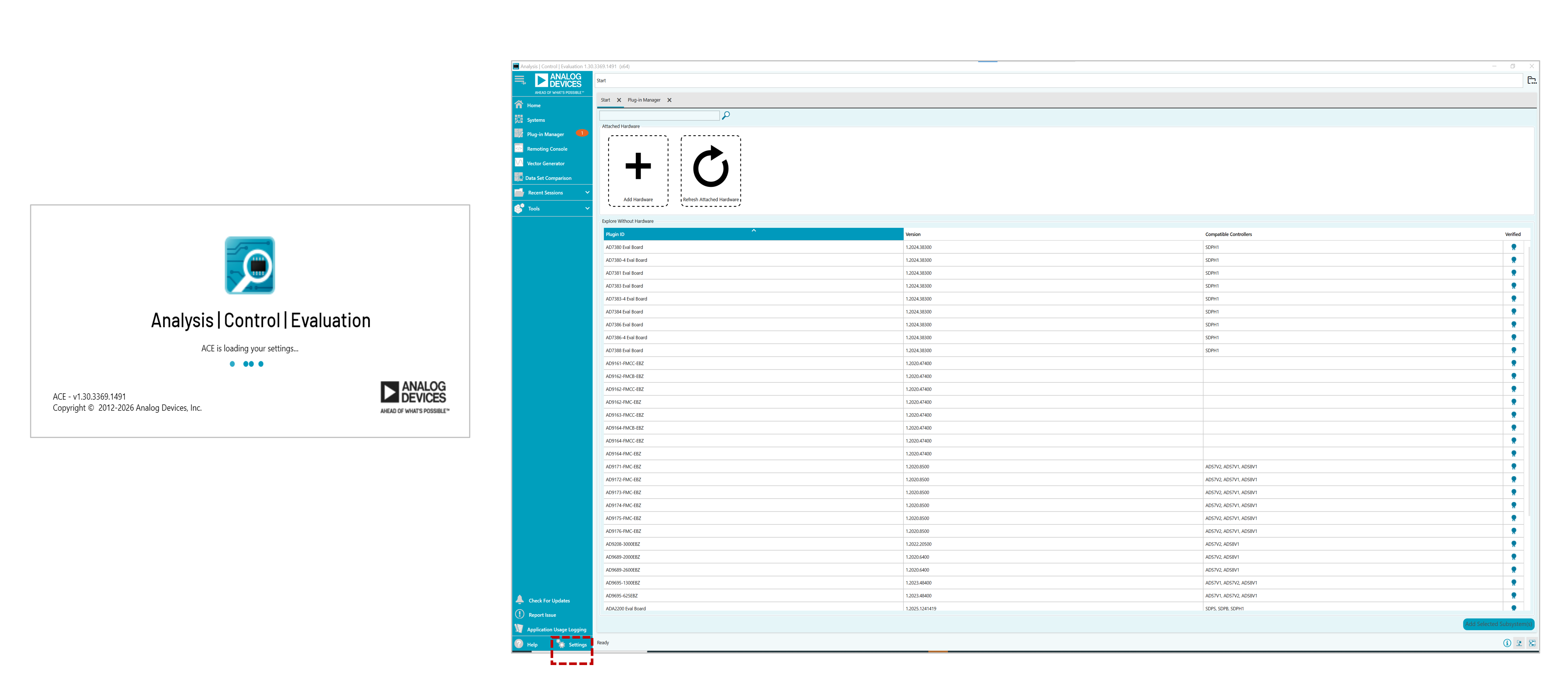
Launch ACE and double-click the plugin.
Open Settings (highlighted in the GUI).
Figure 7 ACE GUI Homepage
Configure Serial Communication
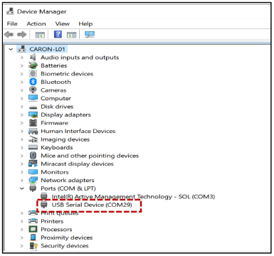
Open Device Manager and note the COM port number.
Figure 8 Device Manager COM Port Detection
In ACE:
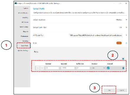
Go to Settings → Serial Ports and add the detected COM port.
Set Protocol = IIO, then Enable the port.
Click OK.
Figure 9 ACE Serial Port Settings
Restart ACE.
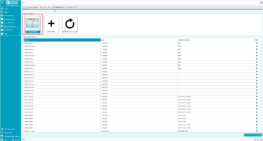
Expected result: The plugin AD-BMSE2E3WLC-48V appears.
Figure 10 ACE Plugin Detection
Note
If the plugin does not appear or load in the ACE GUI, verify the installed libiio version on your PC.
To check the installed version:
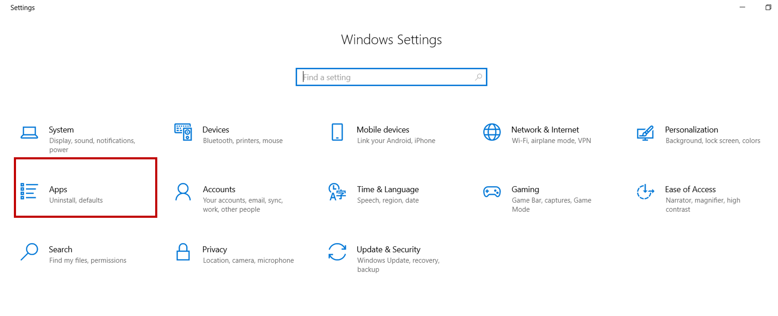
Open ControlPanel → ProgramsandFeatures (or Settings → Apps → InstalledApps).
Figure 11 Control Panel - Programs and Features
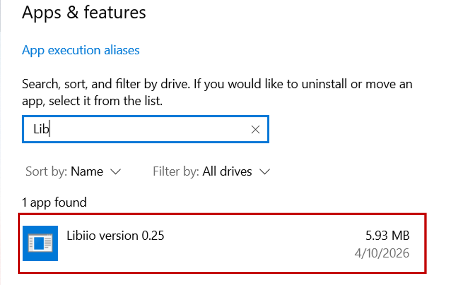
Locate libiio in the list of installed programs.
Verify that the installed version is 0.26.
Figure 12 Installed libiio Version Check
The ACE plugin requires libiio v0.26 to function correctly.
If an earlier version is installed (for example, v0.25), upgrade to v0.26 using the following link:
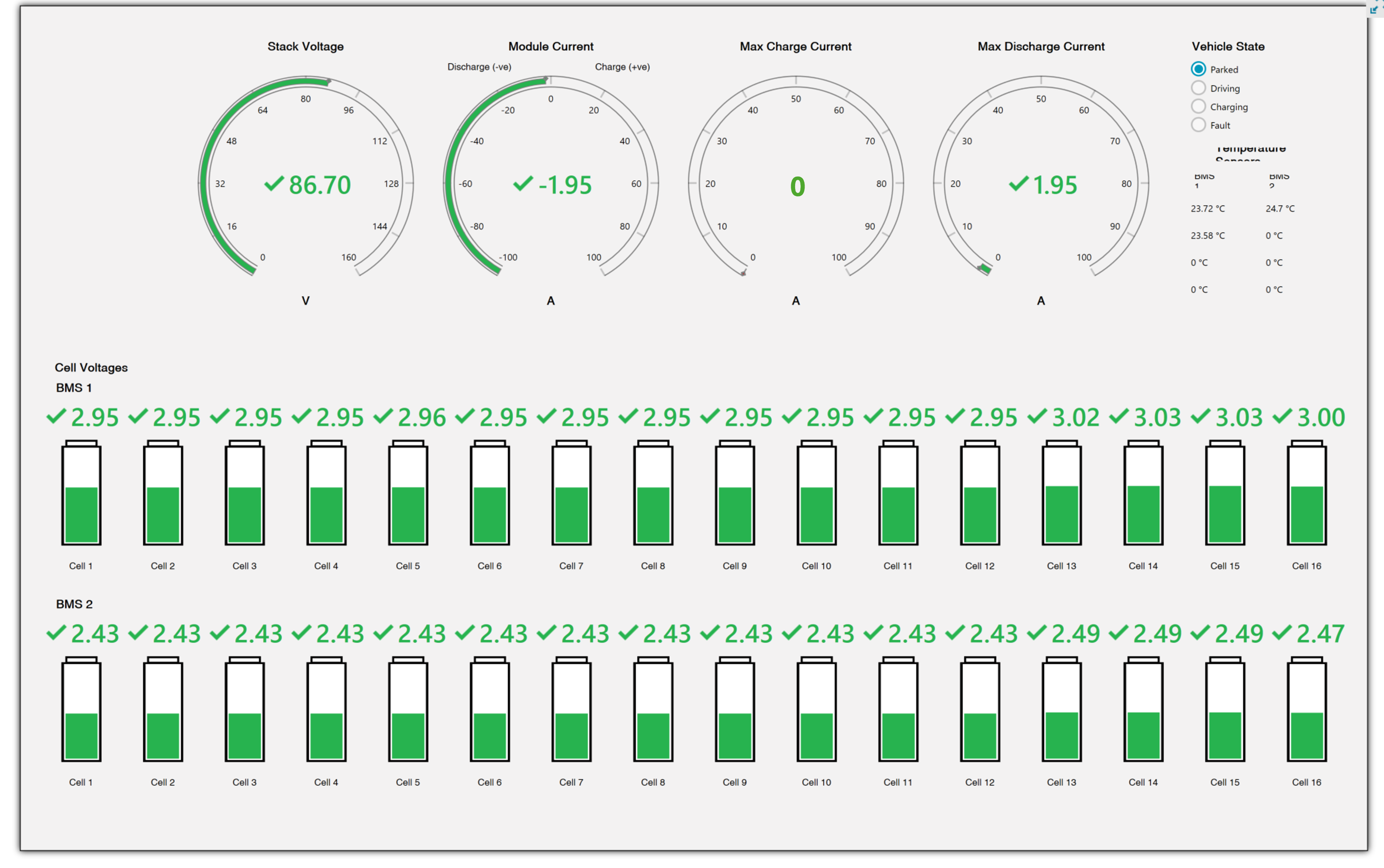
The AD-BMSE2E3WLC-SL GUI provides real-time monitoring of
battery-pack parameters, cell voltages, current measurements,
operating state, and temperature information. The dashboard is
designed to provide a quick overview of battery health and
system status during evaluation and testing.
Figure 13 AD-BMSE2E3WLC-SL GUI
Main Dashboard Layout
The GUI is divided into three primary sections:
System Status Indicators (Top Middle Section)
Vehicle State and Temperature Monitoring (Top Right Section)
Individual Cell Voltage Monitoring (Bottom Section)
Stack Voltage Gauge
The Stack Voltage gauge displays the total voltage of the
battery pack.
Purpose
Monitors overall pack voltage.
Confirms proper connectivity of all battery cells.
Verifies battery charging and discharging behavior.
Displayed Information:
Real-time pack voltage value.
Green indicator showing normal operation.
Gauge range covering the supported battery stack voltage.
Example
Displayed value: 86.70V
Module Current Gauge
The Module Current gauge displays the instantaneous battery
current.
Purpose
Indicates whether the battery is charging or discharging.
Monitors load current and charging current.
Current Direction
Positive (+) current: charging
Negative (-) current: discharging
Example
Displayed value: -1.95A
Indicates that the battery is supplying current to a load.
Max Charge Current Gauge
The Max Charge Current gauge displays the allowable charging
current configured by the BMS.
Purpose
Indicates the maximum current permitted during charging.
May be limited by battery conditions, temperature, or safety
requirements.
Monitoring Use
Verify charging limits before connecting a charger.
Validate BMS protection settings.
Example
Displayed value: 0A
Max Discharge Current Gauge
The Max Discharge Current gauge displays the allowable
discharge current.
Purpose
Indicates the maximum current available to the load.
Helps validate discharge protection behavior.
Monitoring Use
Verify discharge capability during driving conditions.
Observe current-limit changes caused by faults or temperature
restrictions.
Example
Displayed value: 1.95A
Vehicle State Selection
The Vehicle State panel allows the user to select and
monitor the current operating mode.
Available States:
State
Description
Parked
Low-activity mode; output path disabled or
limited.
Driving
Vehicle is actively supplying power to the load.
Charging
Battery is connected to a charging source.
Fault
System enters protection mode due to an
abnormal condition.
Purpose
Vehicle states control the behavior of the BMS and allow users
to evaluate operating-state transitions during system testing.
Temperature Sensors
The Temperature Sensors section displays temperature
measurements from connected thermistors.
Displayed Information
BMS 1 temperature channels
BMS 2 temperature channels
Purpose
Monitor battery-pack temperature.
Verify thermistor operation.
Evaluate thermal protection functionality.
Typical Applications
Overtemperature testing
Thermal characterization
Cell Voltage Monitoring
The lower section of the GUI displays individual cell voltages
for each monitored battery cell.
BMS 1 Cell Monitor
Cells 1 to 16
Individual voltage readings
Battery charge indicators
BMS 2 Cell Monitor
Cells 1 to 16
Individual voltage readings
Battery charge indicators
Visual Indicators
Indicator
Meaning
Green Check Mark
Parameter or cell voltage is within
the normal operating range.
Battery Icon
Visual representation of the cell
level or status.
Green Battery Level
Cell voltage is present and measured
successfully.
Voltage Reading
Actual measured cell voltage value.
Gauge Pointer in Green
Region
Measurement is within expected
operating limits.
Fault State Selected
Protective action is active or a
fault condition has been detected.
The dashboard serves as the primary real-time monitoring
interface for validating pack voltage, current flow, cell
voltages, temperatures, and operating-state transitions during
AD-BMSE2E3WLC-SL evaluation.
Functional Testing Using GUI
Voltage Adjustment Test
Minimum Voltage Test
Rotate both DC2472A knobs clockwise (for the minimum setting).
Expected readings:
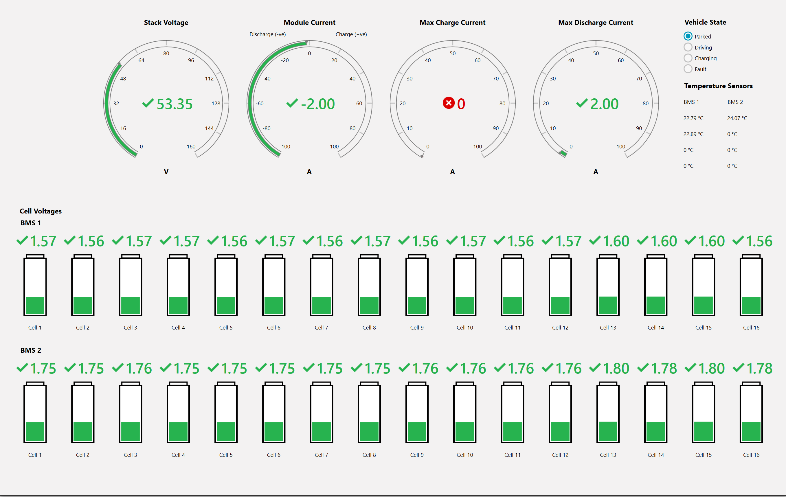
Cell voltage: 1.3V to 1.7V
Stack voltage: decreases
Figure 14 AD-BMSE2E3WLC-SL Minimum Voltage Test
Maximum Voltage Test
Rotate both DC2472A knobs counterclockwise (for the maximum setting).
Expected readings:
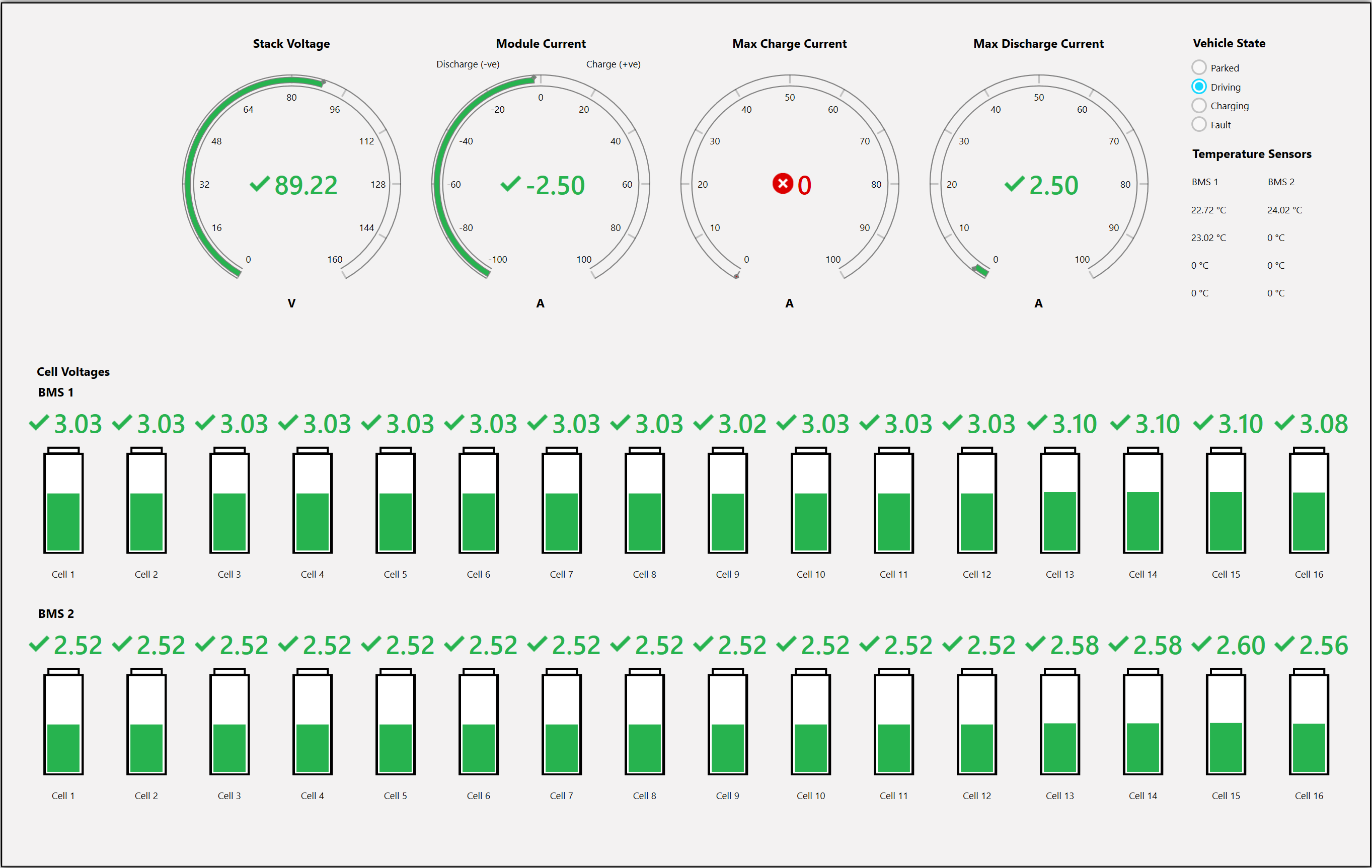
Cell voltage: 4.0V to 5.0V
Stack voltage: increases
Figure 15 AD-BMSE2E3WLC-SL Maximum Voltage Test
You may adjust one emulator at a time to observe the changes clearly.
Output Power Delivery Test
Measure using a Digital Multimeter (DMM):
Connect DMM (–) to Ground.
Connect DMM (+) to TP23.
Expected reading: 4.0V to 4.7V
In GUI:
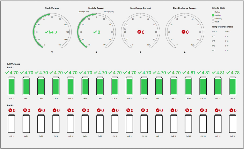
Set Vehicle State = Driving.
Verify the voltage again.
Figure 16 AD-BMSE2E3WLC-SL Power Delivery Test - “Driving” Mode
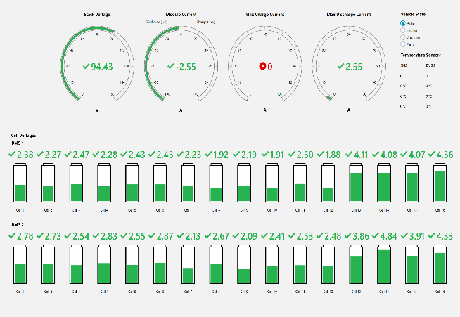
Vehicle State = Parked
Figure 17 AD-BMSE2E3WLC-SL Power Delivery Test - “Parked” Mode
Shutdown Procedure
Follow this sequence to safely power down:
Disconnect power from the MAX32666FTHR microcontroller.
Disconnect power from both DC2472A battery cell emulators.