4-Channel Thermocouple Demo using the Arduino Uno
General Description/Overview
The CN0391_example project uses the EVAL-CN0391-ARDZ Shield which is a multichannel thermocouple temperature measurement system with cold junction compensation.
The EVAL-CN0391-ARDZ shield uses the AD7124-8 part which is a 8-Channel Low Noise, Low Power, 24-Bit, Sigma-Delta ADC with PGA and Reference. All signal conditioning and excitation is performed by the AD7124-8, no additional components are needed.
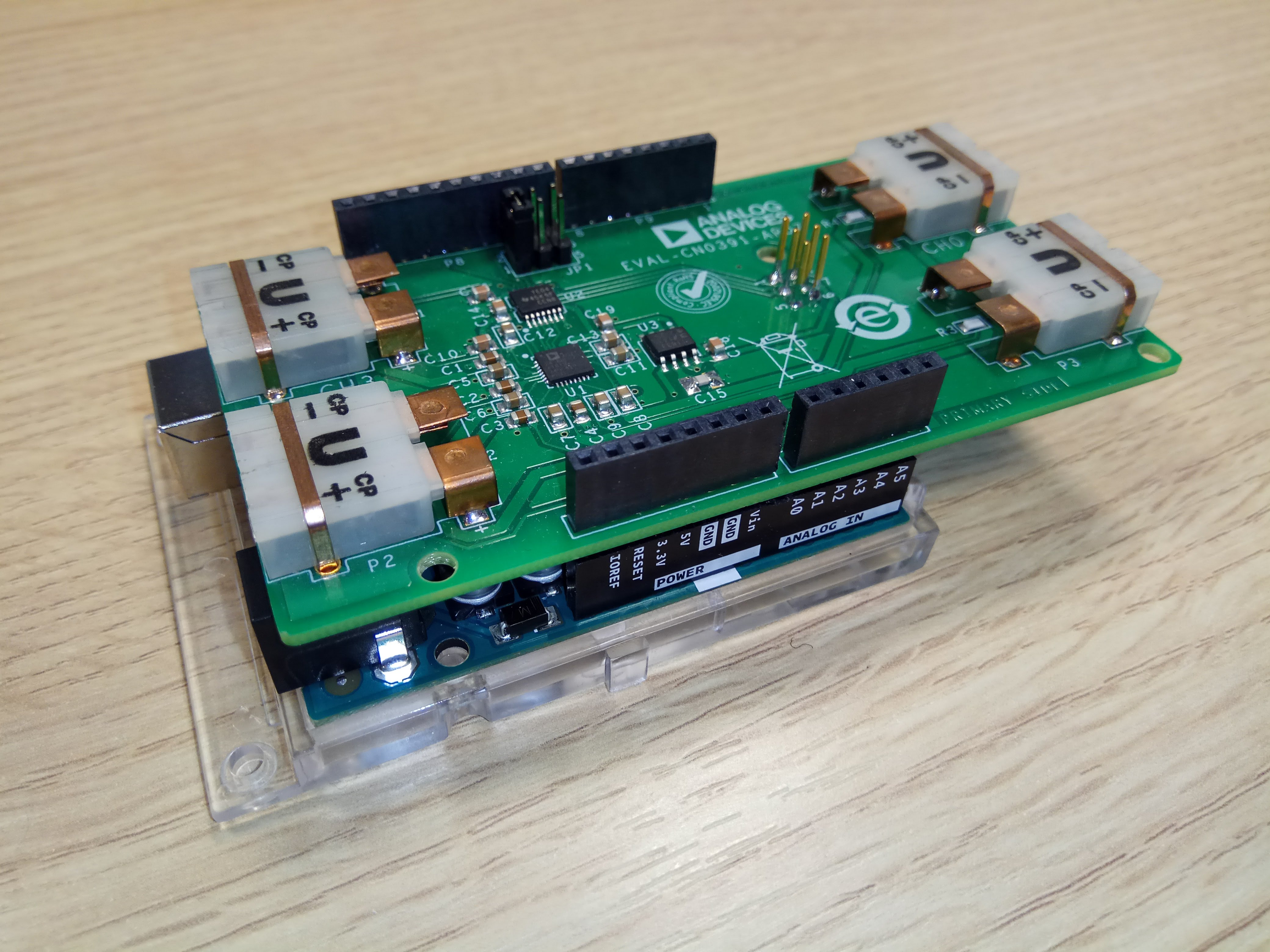
The EVAL-CN0391-ARDZ board has 4 thermocouple ports: P1**~**P4. The board has 4 Pt1000 RTDs: R1**~**R4 close to each thermocouple socket for cold junction compensation. It supports all 8 types of thermocouple: T, J, K, E, S, R, N, B with full range temperature measurement. The RTD operates in the 2-wire mode and the excitation current is generated by the AD7124-8.
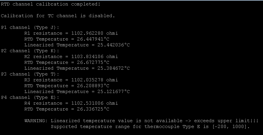
The CN0391_example application reads the 4 RTD channels and the 4 thermocouple channels, processes them, makes all necessary calculations in order to output a linearized temperature for each available port. The UART interface (9600 baud rate, 1 start bit, 8-bits data length, no parity bits and 1 stop bits) is used to send data to a terminal window. The user has the possibility to enable/disable calibration on each channel separately. In the terminal window after initialization will appear information messages regarding this: if calibration is enable then the user will be informed when the calibration is completed, otherwise the user will be informed that the calibration is disabled (see USE_RTD_CALIBRATION and USE_TH_CALIBRATION parameters).
Before starting the measurement it is required to setup the thermocouple types for each port (check P1_TYPE - P4_TYPE). Based on those settings the output data will be calculated and displayed in the terminal window continuously considering a data refresh parameter (see DISPLAY_REFRESH). Also the warning messages will be displayed if the final linearized temperature for the selected thermocouple is out of the boundaries:
Temperature Measurement and Linearization Algorithm
This project uses voltage to temperature solution, based on the cold junction temperature compensation and thermocouple measurements in order to provide a final linearized temperature. The linearization is dictated by thermocouple type and it uses standard formulas generated by the National Institute of Standards and Technology (NIST).
When implementing thermocouple measurements, the thermocouple measures the temperature at the thermocouple relative to the cold junction. The cold junction temperature must be added to give the overall temperature. Converting the thermocouple measured voltage to a temperature requires the data measured to be linearized. Linearization is carried out by using the cold junction temperature together with the voltage generated by the thermocouple.
Cold Junction Measurement
For the cold junction temperature measurement is used PT1000 RTD method. Cold junction reading from each RTD channel is used to calculate RTD resistance:

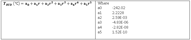
The PT1000 RTD is ideally 1000Ω at 0°C. There are two separate equations that are used for linearization and depending on the calculated resistance it is use one or the other:
1. RTD resistance > 1000Ω

2. RTD resistance ≤ 1000Ω
Note
The second approximation formula was implemented for CN0382 circuit, using data gathered in a smaller temperature range: 0°C to 105°C.
Thermocouple Measurement
For thermocouple temperature linearization are used standard NIST equations. The thermocouple type used dictates the formulas needed for the linearization. First the cold junction temperature needs to be converted to a cold junction voltage. This conversion is implemented using a standard formula. The formula is the same for all thermocouple types. However, the coefficient values used in the formula are dependent on the thermocouple type.

The final thermocouple voltage is calculated using thermocouple voltage read on the thermocouple channel and adding to this value the converted cold junction voltage:
                                             Vtc - final voltage value for themocouple channel
Vtc = Vtc_read + Vcj                         Vtc_read - voltage value measured on thermocouple channel
                                             Vcj - cold junction voltage calculated using first NIST formula
For the final linearized temperature value is used the second polynomial formula provided by NIST standard:

Demo Requirements
The following is a list of items needed in order to replicate this demo.
Hardware
Arduino Uno Rev 3
EVAL-CN0391-ARDZ
Up to 4 Thermocouple Sensors (Type T, J, K, E, S, R, N, B)
Type B to Type A USB cable
PC or Laptop with a USB port
Software
CN0391_example sketch
Arduino Interactive Development Environment(IDE)
Setting up the Hardware
Plug the EVAL-CN0391-ARDZ shield on top of the Arduino Uno development board by matching up the POWER, ANALOG, DIGI0, DIGI1 connectors.
Note, the boards should only plug together one way, preventing reverse connections.
Connect your thermocouple sensor to the EVAL-CN0391-ARDZ via (P1-P4).
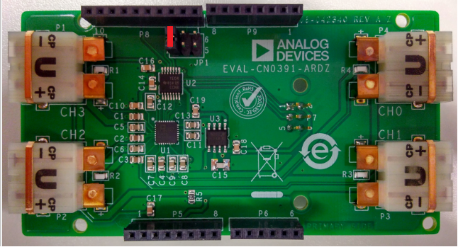
Set the jumper JP1 of EVAL-CN0391-ARDZ board as shown in the picture
Plug in the Type B USB cable into the USB port on the Arduino Uno, and the other end into the PC or laptop.
Obtaining the Source Code
The source code and include files of the CN0391_example can be found here:
Download
Project Structure
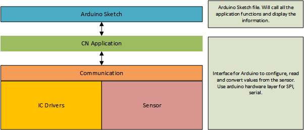
The Arduino Sketch is used to open the example into Arduino IDE. The project is composed of three main parts:
the main program (arduino sketch)
application layer
communication layer
driver layer (IC drivers and sensor data)
Configuring the Software Parameters
Before running your program, make sure that you have configured the software appropriately to your settings:
RTD channel calibration - enable/disable calibration on RTD channel (CN0391.h).
#define USE_RTD_CALIBRATION YES // Set YES to enable calibration on RTD channel, otherwise set to NO
Thermocouple channel calibration - enable/disable calibration on thermocouple channel (CN0391.h).
#define USE_TH_CALIBRATION YES // Set YES to enable calibration on TC channel, otherwise set to NO
Terminal refresh - how often to refresh the output data - input time value in [msec] (CN0391.h).
#define DISPLAY_REFRESH (1000) //ms
Thermocouple types - selects available thermocouple types for each port (Thermocouple.h).
#define   P1_TYPE    TYPE_T      // TYPE_T,TYPE_J,TYPE_K,TYPE_E,TYPE_S,TYPE_R,TYPE_N,TYPE_B
#define   P2_TYPE    TYPE_T      // TYPE_T,TYPE_J,TYPE_K,TYPE_E,TYPE_S,TYPE_R,TYPE_N,TYPE_B
#define   P3_TYPE    TYPE_T      // TYPE_T,TYPE_J,TYPE_K,TYPE_E,TYPE_S,TYPE_R,TYPE_N,TYPE_B
#define   P4_TYPE    TYPE_T      // TYPE_T,TYPE_J,TYPE_K,TYPE_E,TYPE_S,TYPE_R,TYPE_N,TYPE_B
Compiling, Verifying, and Programming
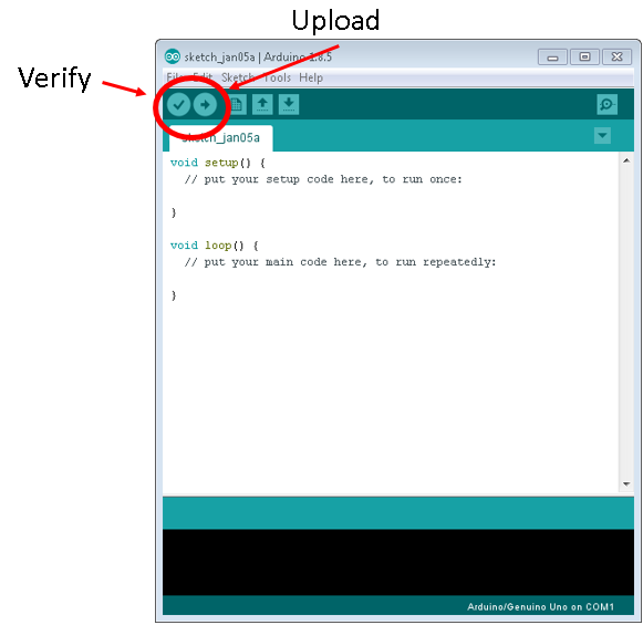
Once the project has been imported and the software parameters have been appropriately configured, you must Compile/Verify the project within the Arduino IDE. You can do this by clicking on the Sketch menu, and then on the Compile/Verify option.
Once the project is compiled and free of errors, you can now upload the project to the Arduino Uno. Click on the Sketch menu item, and then click Upload.
These two steps can also be done using the quick buttons on the Arduino sketch. Check out the image below for locations of the quick buttons.
Outputting Data
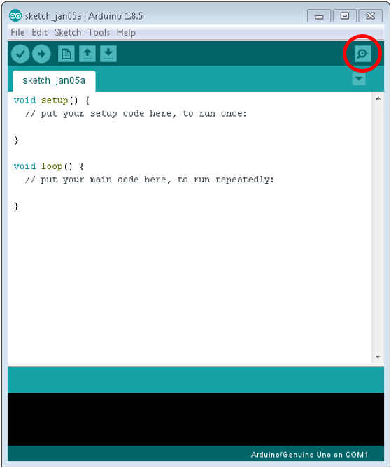
Data is output using the USB cable from the Arduino to the PC. The USB port acts as a serial terminal to display the data being transmitted via UART. Opening the serial terminal window from the Arduino IDE is very easy, simply click on the button shown in the picture below.
Serial Terminal Configuration
You may need to configure the serial terminal depending on the current settings of the Arduino IDE. Make sure the settings are as follows:
Select COM Port of USB device
Baud rate: 9600
Data: 8 bit
Parity: none
Stop: 1 bit
Flow Control: none
Tools Download and Help
The Arduino tools are easy to use, and there are many tutorials and users guides to help learn how to use the Arduino IDE.
For more information on how to use the tool basics, please check out the Arduino tutorials page.
Download
To download the Arduino tools, check out the Arduino software page.
End of Document