Total Dissolved Solids Measurements Demo
The CN0411_example is a Total Dissolved Solids (TDS) measurements demo project, for the Arduino Uno base board with additional EVAL-CN0411-ARDZ shield, created using the Arduino Genuino IDE.
General Description/Overview
The CN0411_example project uses the EVAL-CN0411-ARDZ shield which is a single supply, low power, high precision complete solution for Total Dissolved Solids measurements, including temperature compensation. The circuit is optimized for conductivity measurements used to determine the TDS values, using conductivity cells with BNC plug.
The circuit is divided into three independent measurement front ends: TDS, conductivity and temperature. After signal conditioning, the three channels share an ad7124-8, 24-bit sigma-delta (Σ-Δ) ADC. The ad7124-8, is a low power, low noise, completely integrated analog front end for high precision measurement applications.
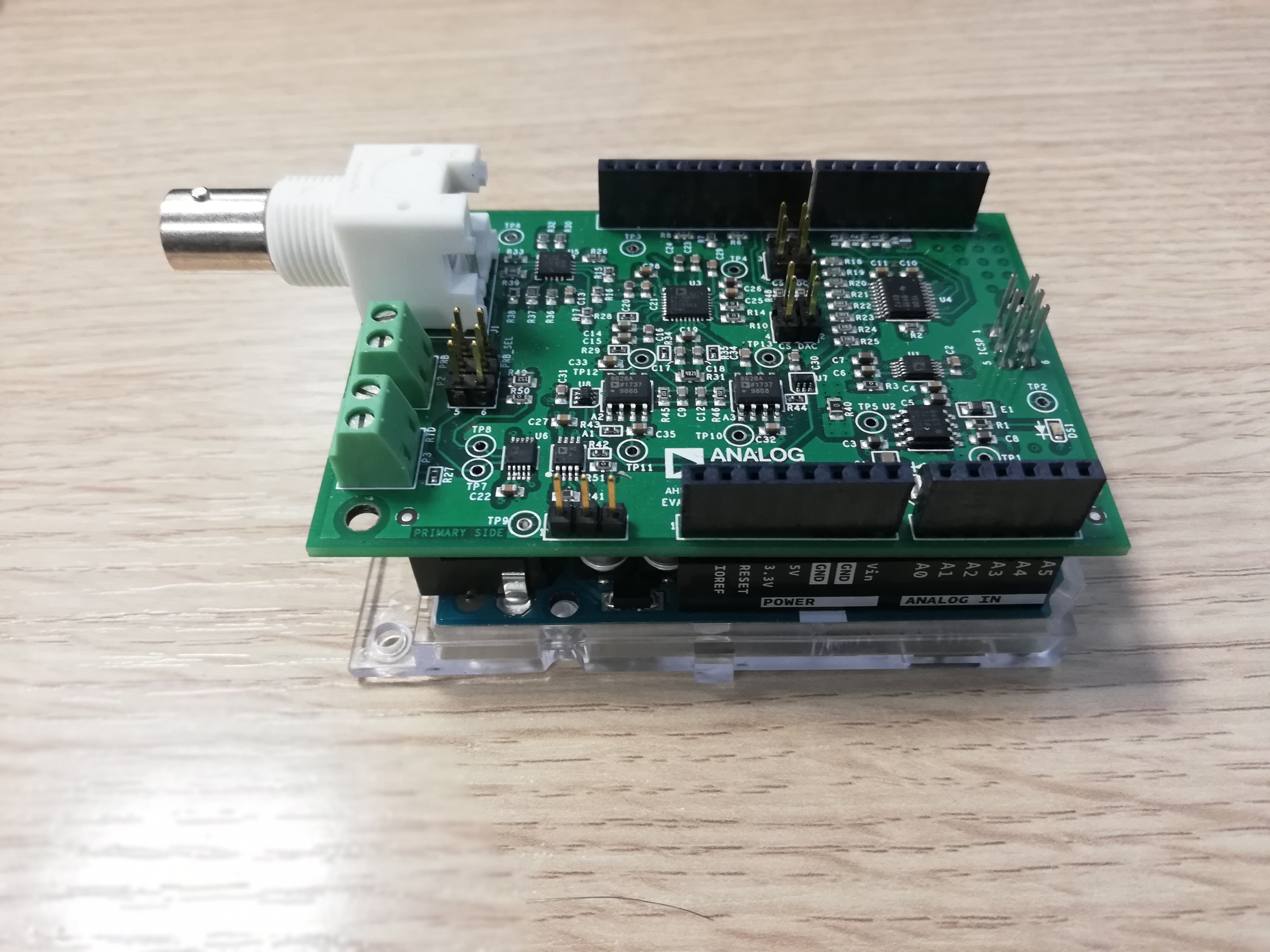
For temperature compensation can be used an RTD PT100 sensor, 2-wire. The CN0411_example application processes ADC outputs for all 5 channels (RTD, Vpeak+ and Vpeak-, VDAC, VR20S, VR200S), calculates conductivity and TDS values using as input RTD temperature value and the peak-to-peak voltage. Those data are sent to serial interface, using UART communication (115200 baud rate and 8-bits data length). The 24-bits ADC data are received using SPI interface of the Arduino Uno board.
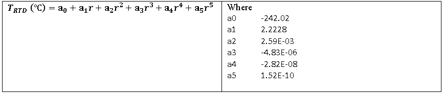
The temperature value is calculated based on the RTD resistance:
Rrtd = (CODE* Rref) / (2^24 -1)                         Rref - Reference resistor (4.02kΩ)
                                                        CODE - ADC output
1. RTD resistance > 100Ω

2. RTD resistance ≤ 100Ω
In order to compute the total dissolved solids parameter a premeasurement procedure is run in the first place that aims to select the proper gain resistance for the measurement.
The multiplexer is set to the highest gain resistance (20MΩ) and the DAC output to a value set by the user (initially set to 400mV). Then, the positive and negative input voltage are captured via ADC channel 1 and 2. If the following formula is met:
                                         Vp = positive input voltage
Vp + Vn > 0.3 * 2 * Vexc                 Vn = negative input voltage
                                         Vexc = DAC output voltage
The excitation voltage used for computing tds is set to:
Vexc = 0.4 * Vexc / (Vp + Vn)
Otherwise, the gain resistor is dropped by 1 decade and the premeasurement process is repeated.
After the process is finished, the peak-to-peak voltage is measured again an the peak-to-peak current is computed:
                                           Ipp = peak-to-peak current
Ipp = (2 * Vexc - (Vp + Vn)) / Rgain       Vexc = excitation voltage computed in the premeasurement procedure
                                           Vp = positive input voltage
                                           Vn = negative input voltage
                                           Rgain = gain resistor set via multiplexer
Based on the peak-to-peak current the electrical conductance is computed, also removing the offset resistance (optional) that is obtained via the software command “refres” found in the list of available commands :
g = Ipp / ((Vp + Vn) - (Ipp * Roff))       Roff = offset resistance
                                           g = electrical conductance
The electrical conductivity is computed using the conductance and the cell constant which can be set accordingly for low conductivities, normal conductivities and high conductivities via software commands. A temperature compensation is also performed taking into account the temperature measured via RTD resistance.
                                                   s = electrical conductivity
s = k * g                                          s_cal = temperature compensated electrical conductivity
                                                   temp_coeff = solution temperature coefficient
s_cal = s / (1 + temp_coeff * (temp - t_cal))      temp = measured temperature
                                                   t_cal = reference temperature (25°C)
The calculation of total dissolved solids is the product between the temperature compensated conductivity and the tds factor corresponding to the solution that is used.
tds = k_e * s_cal                                  k_e = tds factor
                                                   tds = total dissolved solids
Demo Requirements
The following is a list of items needed in order to replicate this demo.
Hardware
Arduino Uno
EVAL-CN0411-ARDZ
Conductivity cell with BNC Connector
PT100/PT1000 RTD probe
USB type B to USB type A cable
PC or Laptop with a USB port
Software
CN0411_example software
Arduino/Genuino IDE
Arduino AVR Boards Built-In by Arduino package (1.6.23 or higher)
Setting up the Hardware
Connect the EVAL-CN0411-ARDZ Shield to the Arduino connectors DIGITAL (PWM~), POWER, ANALOG IN and ICSP of the Arduino Uno board.
Connect the conductivity cell to the J1 connector of the EVAL-CN0411-ARDZ.
Connect the RTD sensor to the P3 connector of the EVAL-CN0411-ARDZ.
Connect PIN1 and PIN2 on P5 connector and PIN1 and PIN2 on P6 connector to read data from the conductivity cell.
Plug in the USB cable from the PC to the Arduino Uno base board via the type B port on the board.
Obtaining the Source Code
We recommend not opening the project directly, but rather make a local copy in your workspace and open it using Arduino/Genuino IDE.
The source code and include files of the CN0411_example can be found here:
Download
Configuring the Software Parameters
DAC default output value - DAC_OUT_DEFAULT_VAL - set default output voltage for the DAC. (CN0411.h).
#define DAC_OUT_DEFAULT_VAL 0.4
KCl solution TDS factor - TDS_KCL - set the TDS factor for the KCl solution. (CN0411.h).
#define TDS_KCL 0.5
NaCl solution TDS factor - TDS_NACL - set the TDS factor for the NaCL solution. (CN0411.h).
#define TDS_NACL 0.47
KCl solution temperature coefficient - TEMP_COEFF_KCL - set the temperature coefficient for the KCl solution. (CN0411.h).
#define TEMP_COEFF_KCL 1.88
NaCl solution temperature coefficient - TEMP_COEFF_NACL - set the temperature coefficient for the NaCl solution. (CN0411.h).
#define TEMP_COEFF_NACL 2.14
Outputting Data
Serial Terminal Output
In order to view the data, you must flash the program to the Arduino Uno board by pressing the Upload button in the IDE.
Once complete Press the serial monitor button.
Make sure the UART settings are “Both NL and CR” and “115200 baud”.
Following is the UART configuration.
Both NL and CR
115200 baud
The user must press the <ENTER> key to start the program.
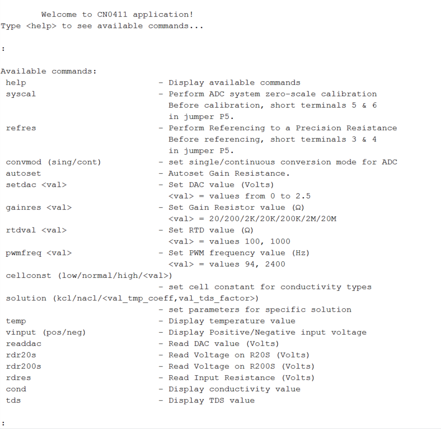
To get to the command menu the user must type <help> into the serial program.
Available commands
Command |
Description |
|---|---|
help |
Display available commands |
syscal |
Perform ADC system zero-scale calibration. Before calibration, short terminals 5 & 6 in jumper P5. |
refres |
Perform Referencing to a Precision Resistance. Before referencing, short terminals 3 & 4 in jumper P5. |
convmod(sing/cont) |
set single/continuous conversion mode for ADC. |
autoset |
Autoset Gain Resistance. |
setdac<val> |
Set DAC value (Volts). |
gainres <val> |
Set Gain Resistor value (Ω). <val> = 20/200/2K/20K/200K/2M/20M |
rtdval <val> |
Set RTD value (Ω). <val> = values 100, 1000 |
pwmfreq <val> |
Set PWM frequency value (Hz), <val> = values 94, 2400 |
cellconst (low/normal/high/<val>) |
Set cell constant for conductivity types. |
solution (kcl/nacl/<val_tmp_coeff,val_tds_factor>) |
Set parameters for specific solution. |
temp |
Display temperature value. |
vinput (pos/neg) |
Display Positive/Negative input voltage. |
readdac |
Read DAC value (Volts). |
rdr20s |
Read Voltage on R20S (Volts). |
rdr200s |
Read Voltage on R200S (Volts). |
readdac |
Read DAC value (Volts). |
readdac |
Read DAC value (Volts). |
rdres |
Read Input Resistance (Volts). |
cond |
Display conductivity value. |
tds |
Display TDS value. |
Project Structure
The CN0411_example is a C Arduino sketch.
This project contains: system initialization part - setting Digital IO pins in the right mode; port configuration for ADC, SPI read/write; for configuring and reading from AD7124, UART via Digital pin 0/Digital pin 1; UART read/write functions; for calibration and displaying the results.
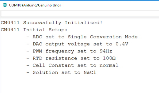
All files are in the same folder as the .ino file and include the source and header files related to CN0411 software application. The Communication.c files contain SPI and UART specific data, meanwhile the CN0411.c files contain the calculation part, the AD7124.c files contain ADC channels handling. The default parameters are set at the run time, after initialization in the terminal window will appear information messages about the initial setup.
End of Document