User Guide for EVAL-ADuCM360
Introduction
The ADuCM360 is a fully integrated, 4 kSPS, 24-bit data acquisition system that incorporates dual, high performance multichannel sigma-delta (Σ-Δ) analog-to-digital converters (ADCs), a 32-bit ARM Cortex™-M3 processor, and Flash/EE memory on a single chip.
The ADuCM360 is designed for direct interfacing to external precision sensors in both wired and battery-powered applications. The ADuCM361 contains all the features of the ADuCM360 except for the ADC0, which is removed.
Refer to ADuCM360/ADuCM361 for future updates. Additional support is available through Engineer Zone - Precision Microcontrollers
General Description
The EVAL-ADuCM360 Development System allows evaluation of ADUCM360 silicon. This getting started guide introduces the support features and the tools supplied with the evaluation kit. In addition, it shows and describes how to connect the evaluation hardware.
This guide works as a tutorial by providing a step-by-step account of how to download evaluation versions of third-party software tools. Instructions are provided on how to load code examples that are supplied with the ADuCM36x Software Pack. These examples demonstrate simple operation of the ADuCM360.
Working through this guide brings the user to the stage where they can start to generate and download their own user code for use in their own unique end-system requirements.
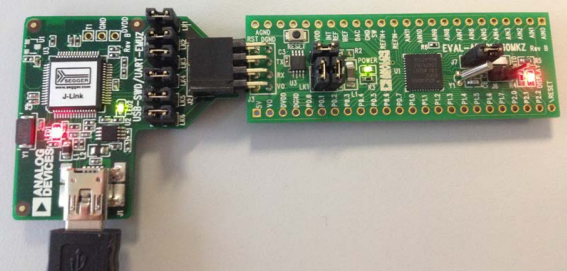
Figure 1. EVAL-ADuCM360 Development System Connected to Analog Devices, inc. J-Link OB Emulator
Development System Contents
The EVAL-ADuCM360QSPZ is an evaluation kit for the ADuCM360 and ADuCM361. This kit features a mini-board (EVAL-ADuCM360MKZ) and an Analog Devices J-Link OB emulator (USB-SWD/UART-EMUZ) that connects to a PC USB port via a USB cable. A comprehensive set of development tools is available for download, as described in the Software Installation section.
The development system contains the following:
An ADuCM360 mini-board
An Analog Devices J-Link OB emulator
1 USB cable
Evaluation Board
The EVAL-ADuCM360QSPZ mini-board facilitates performance evaluation of the device with a minimum of external components.
J-LINK OB Emulator
The J-Link OB emulator provides nonintrusive emulation via a serial wire, and also provides supply and UART communication with the ADuCM360 mini-board. Figure 2 shows a top view of the emulator board. J2 connector plugs into the ADuCM360mini board. The J2 connector pinout is shown in Figure 3.
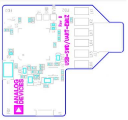
Figure 2. Emulator Top View
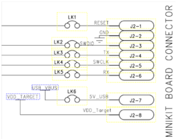
Figure 3. J2 Connector
For downloading and debugging, LK1, LK2, LK4, and LK6 must be inserted. LK3 and LK5 are required to communicate via UART. Required software for the J-Link OB is included in the software installation. Note that the J-Link OB emulator replaces the J-Link Lite and related interface boards previously shipped with the ADuCM360 development system.
Connecting the Hardware
Do not plug in the emulator and mini-board before the software is installed. See the Software Installation section.
Software Installation
The development tools can be downloaded from the ADuCM360 product website or through the links below.
Software Content Provided
The table below shows the tools provided.
Tools |
Functions |
|---|---|
Keil μVision |
For compiling/debugging and code development, a 32 kB limited version. For latest version Keil Downloads |
IAR Embedded Workbench for ARM |
For compiling/debugging and code development, a 32 kB limited version. For latest version IAR Embedded Workbench for ARM |
Software Pack |
ADuCM36x Device support and examples. For Keil μVision, it can be downloaded here or installed through Keil uVision. For IAR Embedded Workbench, it can be installed through the application |
Segger J-Link Software |
J-Link software and documentation pack. Includes USB drivers for the emulator, J-Link commander, J-Flash and so on. J-Link Software and Documentation Pack |
CM3WSD |
This utility accepts a hex file and allows it to be downloaded via the USB interface to the ADuCM360 device on your evaluation board |
Software Installation Instructions
Perform the steps described in this section before plugging in any of the USB devices into the PC.
Close all open applications.
Download and install the latest version of Keil μVision 5 MDK-ARM or IAR Embedded Workbench for ARM, as preferred.
Download and install the ADuCM36x Software Pack. See Installing ADuCM36x Software Pack
Download and install the J-Link Software and Documentation Pack. This installs the J-Link serial port driver. Keep the default settings that appear in the next Segger messages windows.
The Segger J-Link software is selected by default in the installation menu and it is advised to leave it selected. This automatically installs the J-Link serial port driver (keep the default settings that appear in the next Segger messages windows).
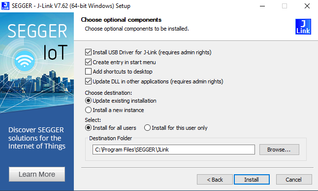
Figure 4. Installing Segger J-Link Software
Although the Keil™ software can be installed onto any hard drive and into any directory, for the purposes of simplicity, this user guide assumes it is installed at the default location of C:\keil_v5, and the ARM packs are installed in C:\Users\<user>\AppData\Local\Arm\Packs
Programs Installed
The software described in this section has now been copied or installed.
CM3WSD.exe The folder \ADuCMxxxV1.3\Software Tools\CM3WSD provides an executable called CM3WSD.exe. This software accepts a hex file and allows it to be downloaded via the USB interface to the ADuCM360 device on your evaluation board. You may want to add a shortcut link for this executable to your desktop.
elves.exe The \ADuCMxxxV1.3\Software Tools\Elves folder contains the elves.exe files. These files are useful tools that accompany the software function libraries in \ADuCMxxxV1.3\Code\ADuCM360\common. Again, no installation is required here, but you may want to add a shortcut link for this executable to your desktop.
Driver The J-Link OB emulator requires a driver, which is installed automatically when the Segger J-Link Software is selected (see Step 4 of the Software Installation Instructions section). At this point, check that the driver is installed correctly. Plug in the emulator and check the device manager (see Figure 5). Check that it appears in the Windows Device Manager in both the communications port and the USB controllers lists.
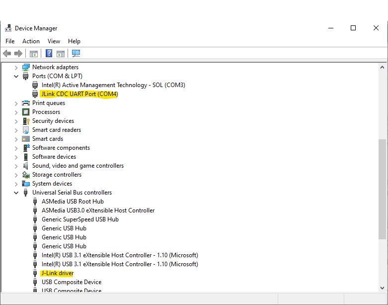
Figure 5. Device Manager
Keil μVision5 Integrated Development Environment
Introduction
The μVision5 Integrated Development Environment (IDE) integrates all the tools necessary to edit, assemble and debug code. The ADuCM360 development system supports nonintrusive emulation limited to 32 kB code.
This section describes the project setup steps in order to download and debug code on an ADuCM360 Evaluation System. Analog Devices recommends using the J-Link debugger driver.
Quick Start Steps
From the Start Menu, choose Keil μVision5. This loads the μVision5 IDE. the μVision5 executable is located at C:\Keil_v5\UV4\UV4.exe
To open one of the prepared Keil μVision5, click on the Pack Installer (Figure 6)
Search for aducm in the search bar on the left
Select ADuCM36x Series
Select the Examples tab on the right
Click on Copy on the RTD_Demo Example (Figure 7)
Select the path where you want the example code to be copied. For example: C:\Analog Devices\ADuCM36x. Leave Use Pack Folder Structure and Launch μVision selected and click OK
Once the example has been copied, a new instance of Keil μVision5 with the example project opens. (Figure 8)
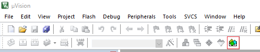
Figure 6. Opening Keil Package Installer
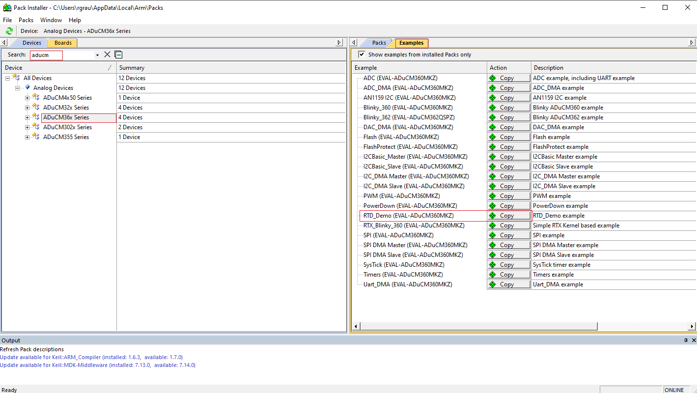
Figure 7. Copying an example into a new project
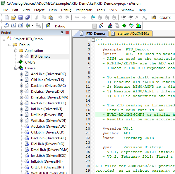
Figure 8. RTD Example Project
To compile and build all files, select the Build All icon.

Once the build has completed, the code shown in Figure 9 appears.
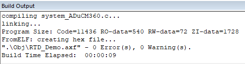
Figure 9. Build Output
To download the code to the EVAL-ADuCM360MKZ board and begin a debug session, connect the J-Link OB emulator to the EVAL-ADuCM360MKZ mini-board and to your PC using the provided USB cable.
In μVision, click the Start/Stop Debug session icon.

Begin debugging your source code.
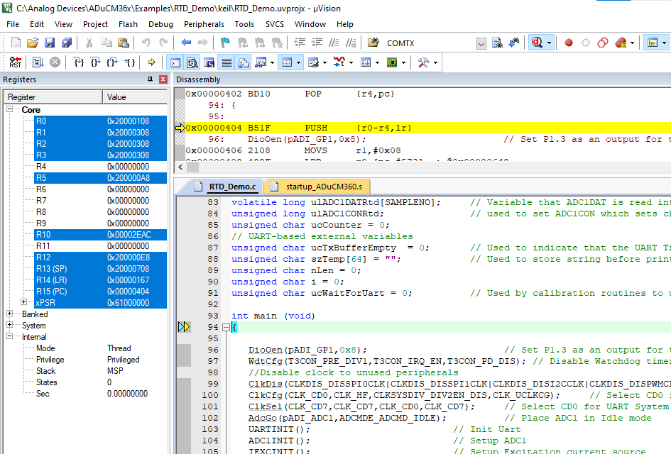
Figure 10. Debug Source Code
Extra Optional Details on Keil μVision
This section provides a more detailed explanation of the setup described in the Quick Start Steps section.
Starting a Project
Under the View menu, two toolbars are available:
File toolbar
Build toolbar/Debug toolbar
The File toolbar is always available. The Build toolbar is active only when the IDE is in edit/compile mode. The Debug toolbar is active only in download/debug mode.
Creating a New Project
From the Project menu, select New μVision Project.
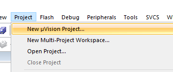
Project Menu
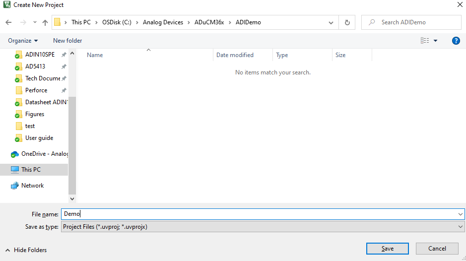
Create a new folder (ADIDemo). To do so, go to C:\Analog Devices\ADuCM36x\ADIDemo and enter Demo as the project name.
In the Select Device for Target ‘Target 1’ window, select Software Packs and select ADuCM360
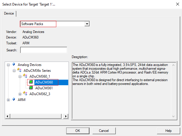
Select Device
In the Manage Run-Time Environment select the desired drivers to import to the project. For our example, select CMSIS -> CORE, Device -> Startup, and all the drivers in Device -> Drivers, and click OK.
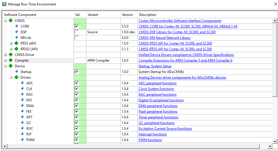
Manage Run-Time Environment
In the project window, right-click on Target1 and select Options for Target ‘Target1…’
Select the Target tab.
Ensure the IROM1 and IRAM1 Start and Size fields are filled as shown in the picture below
In ARM Compiler, select Use default compiler version 5
Ensure that the Use MicroLIB option is enabled.
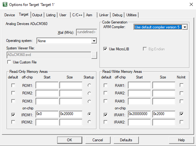
Target Options
Select the Linker tab and then select Use Memory Layout from Target Dialog
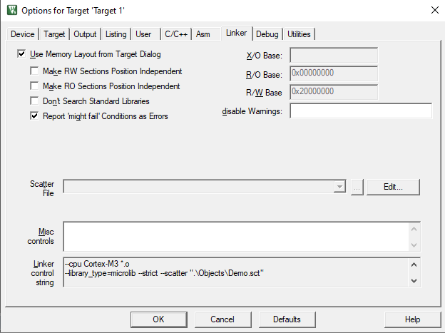
Linker Options
In the Output tab, select Create HEX File. The hex file can be used by the JLINK Commander. Then select OK.
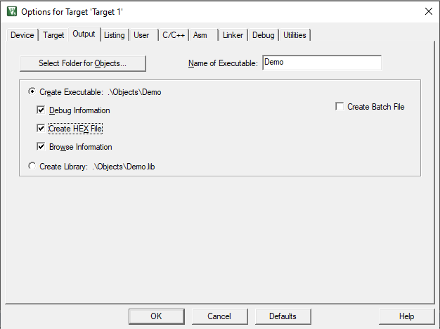
Output Options
Connect the emulator to the ADuCM360 mini-board and to your PC’s USB port using a USB cable. Note that an LED on the J-Link OB emulator blinks several times before staying on, indicating that the emulator is communicating correctly with the PC.
Configuring the J-Link Debugger Driver
In the project window, right-click on Target1 and select Options for Target ‘Target1…
In the Debug tab, select Use: and then select J-LINK/J-Trace Cortex, and tick Run to main(). Click on Settings.
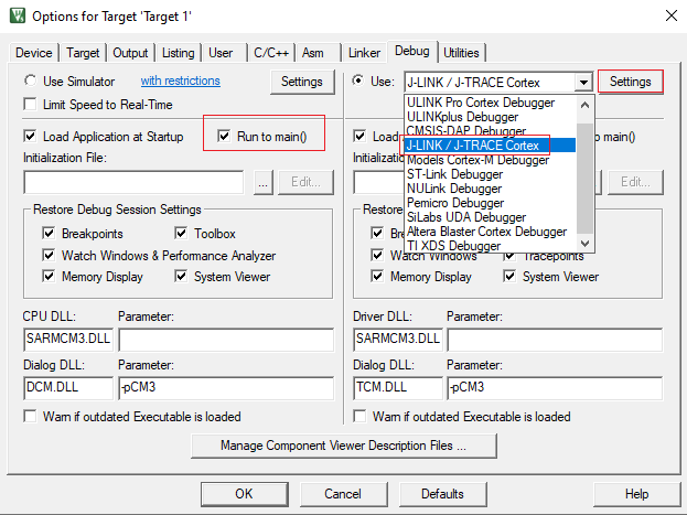
Selecting a debugger
Configure the Cortex JLink/JTrace Target Driver Setup window as in the following picture:
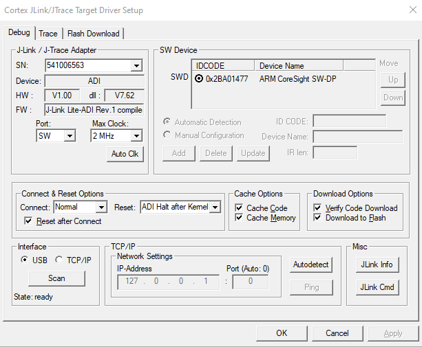
J-Link Target Driver Setup
Select OK
Under the Utilities tab, select Use Target Driver for Flash Programming. Then, select Use Debug Driver and select the option Update Target before Debugging.
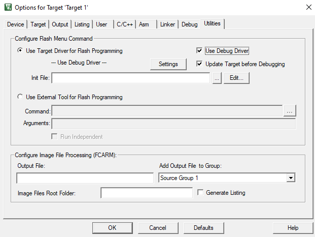
Configuration of the Utilities Menu
Click on Settings, and check that the Flash Download tab is configured as the following picture:
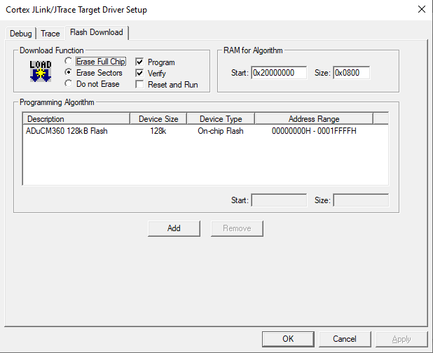
Flash Download Setup
Select OK. All the options should be properly configured to compile, assemble, download and debug using J-Link Lite.
Adding Project Files
At this point you can create and add your source code files necessary for your development. For this example, we are adding the main source file of an example project.
Copy the file C:\Users\<user>\AppData\Local\Arm\Packs\AnalogDevices\ADuCM36x_DFP\1.0.4\Examples\ADC\ADCMeter.c into the new project directory: C:\Analog Devices\ADuCM36x\ADIDemo
To add the file to the project, right-click on the Source Group folder in the Project window, and select Add Existing Files to Group ‘Source Group 1…’
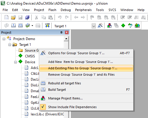
Adding existing files to the project
Add the file ADCMeter.c
Double click on ADCMeter.c in the Project window to open the file.
Assembling/Compiling/Downloading Code
To compile/link ADCMeter.c, press Ctrl+F7 or click on the translate icon in the toolbar. The file should compile correctly and the Build Output Window should say “ADCMeter.c” - 0 Error(s), 0 Warning(s). If there are any errors in your source code, these appear in the status window. To identify the line of code that corresponds to the error, double-click on the error in the Build Output window and an arrow highlights the line of code in error.
Before the code can be downloaded to the ADuCM360, the entire project must be build. This is done by clicking on the Rebuild icon on the toolbar. It will also create a demo.elf file used by the debugger.
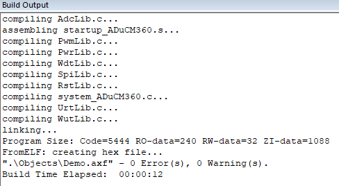
Build Project Successful
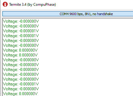
The code can now be downloaded into the ADuCM360 clicking on the Load icon in the toolbar. Press the Reset button on the board, and the code starts running on the ADuCM360. The program measures the input signal applied across AIN0 and AIN1, converts this to a voltage, and sends this information in an ASCII string to the UART - baud rate 9600-8-N-1.
IAR Embedded Workbench for ARM IDE
The IAR Embedded Workbench IDE for ARM integrates all the tools necessary to edit, assemble, and debug code. The ADuCM360 development system supports nonintrusive emulation limited to 32 kB code.
This section describes the project setup steps in order to download and debug code on an ADuCM360 Evaluation System. Analog Devices recommends using the J-Link debugger driver.
Starting IAR Embedded Workbench
From the Start Menu, choose IAR Embedded Workbench for ARM -> IAR EW For ARM. This loads the IAR Embedded Workbench IDE.
Quick Start Steps
Follow the steps in this section to get up and running with the example code provided with the evaluation software.
These steps use the default driver and compiler settings.
To open the prepared IAR example projects click on the CMSIS-Pack Manager

A prompt to create a new Workspace will appear. Select the desired Folder and name to save it. (Figure 11)
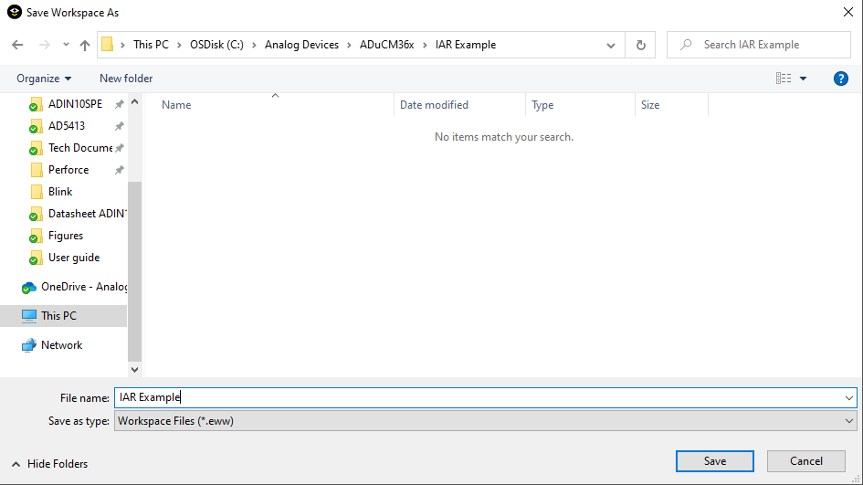
Figure 11. Creation of a new Workspace
The CMSIS Manager will launch. Select the Devices tab, and search for aducm in the Search Device bar. Select ADuCM360
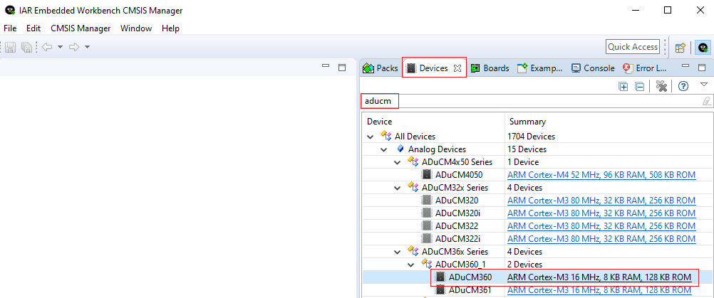
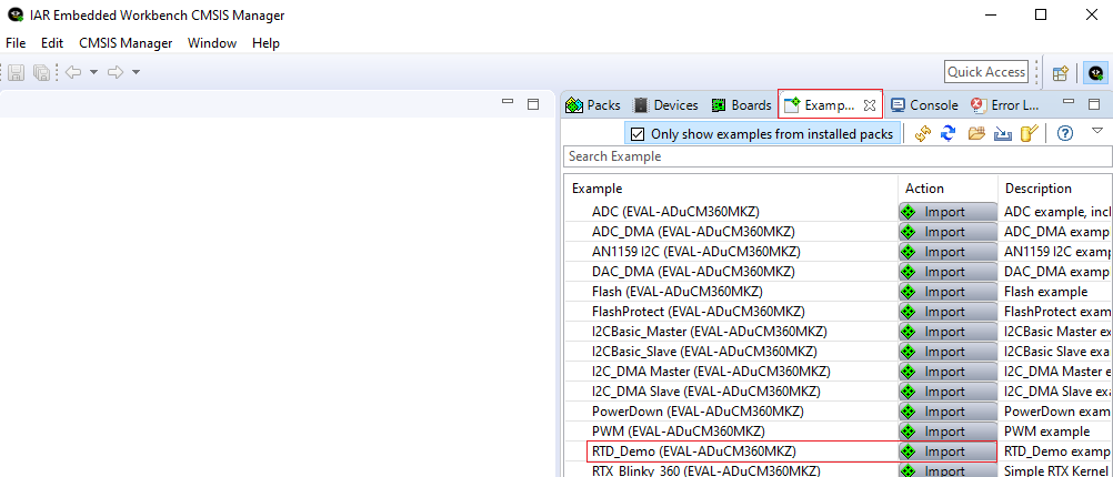
With the ADuCM360 device selected, change to the Examples tab. Import the desired example, for example RTD_DEMO
The example is imported into the workspace, as can be seen in Figure 12.
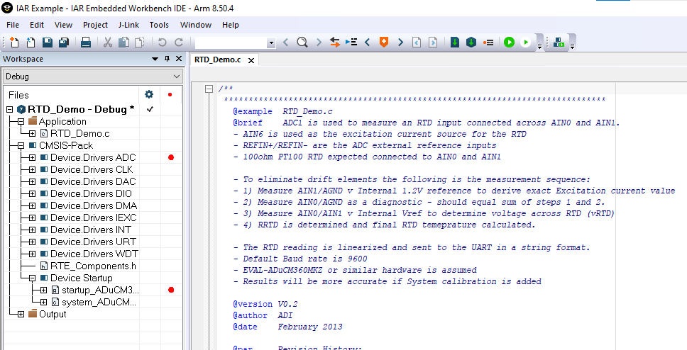
Figure 12. RTD_Demo example
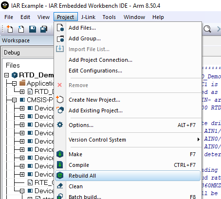
To compile all files, select Project -> Rebuild All
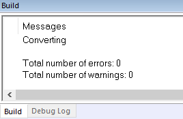
If the Build is successful, the information is displayed in the Build details window.
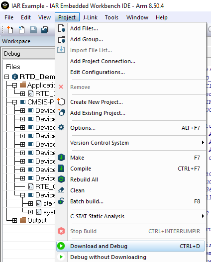
To program the device and begin debugging the source code, select Project -> Download and Debug
Downloading Code into Flash
Windows Serial Downloader
The Windows(r) Serial Downloader for Cortex-M3 based parts (CM3WSD) is a Windows software program that allows a user to serially download Intel Extended Hex files as created by the assembler/compiler to the ADuCM360 via the serial port.
The Intel Extended Hex file is downloaded into the on-chip Flash/EE program memory via a selected PC serial port.
Preparing for Download
Connect the ADuCM360 mini-board (EVAL-ADuCM360MKZ) to the emulator board, and the emulator board to the PC using a USB cable.
Ensure all the links are inserted in both boards.
Place the ADuCM360 into serial download mode using the following sequence.
Pull P2.2 low.
Pull the RESET pin low and then high (float).
P2.2 can be left floating once RESET is high.
Downloading using CM3WSD
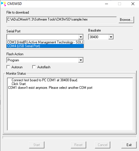
In the Start Menu, open CM3WSD.
Click on Browse and select the desired .hex file.
In the Serial Port drop-down menu, select USB Serial Port and a baudrate of 38400.
Select Start The CM3WSD sends a reset command to the ADuCM360. If the ADuCM360 is in serial download mode and the COM port between the PC and the mini-board is setup correctly, then the CM3WSD starts download the hex file and display a progress bar while the file is downloading. Once the file has been successfully downloaded, the monitor status box is updated with Flashing Complete Click Reset to run program.
Running the Downloaded File
Running using CM3WSD
Select Reset with P2.2 floating or pulled high. The monitor status box updates with the message Running
Manual Run Option
Pull RESET low, then high (or float) on the mini-board to reset the ADuCM360 with P2.2 floating or pulled high. The program starts running automatically.